Friday, 20 May 2022

Laser-line Oche for Dartboard

When I built the dartboard cabinet last year, I put a piece of tape on the floor to act as an oche (throw line).

As they say, there's nothing more permanent than a temporary solution, and a year later, the tape was still there, so now it's time to do something about it.

Years ago, back when I first started posting my projects on social media, one of my first Instagram posts was about a (now long abandoned) project to create a 3D scanner:


In this process, a regular laser diode - like one from a laser pointer - is aimed through a transparent cylindrical object. This acts like a prism, refracting the light, creating a line.

The same principle I used back then, is what I'm using this time around. Although this time I'm using a piece of acrylic rod rather than being cheap and trying to use a stem from a broken wine glass...

The Diode

The laser diode that I'm using comes from an old Nintendo Wii lightgun accessory, and was the one I started using in the laser scanner project.


With all the plastic shroud removed, this is what is we're left with


 The Casing

I initially went down the rabbit hole of making a 3D printed case, but in a moment of inspiration, realised that a short section of copper pipe would be perfect.

The pipe is about 1.5 inches long, and we're using two end caps.

One simply has a small hole drilled for the wires to come out of the back


A plastic washer was used to create a mount for the laser diode in the pipe.

The second pipe end cap is used to create the lens assembly.


The lens assembly

A hole was drilled into the end cap, bevelled at the outside for a nicer finish. The hole should be no wider than the diameter of the acrylic rod.

A small piece of transparent acrylic rod was cut, and sanded to make a friction fit in the end cap perpendicular to the hole that was drilled.


You can see how the rod bends the light, making the drilled hole look square.

This lens assembly can be push fit over the end of the rod.


The wiring

The diode was powered by 2 AAA batteries, so I found a 3.7V phone charger as the closest contender for a power source. However, it's not just a case of connecting the diode to the charger.

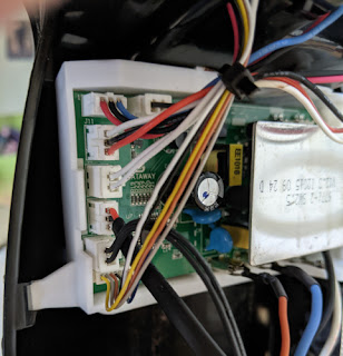
It's important that laser diodes are driven correctly as current fluctuations can easily damage them. In some cheap laser pointers, control of the current is sometimes limited by the specification of the batteries that are used.

I was expecting this to be the case with this one, but after some probing, I determined that I was lucky, this laser contained some control circuitry (behind the yellow shrink-wrap in the diode picture).

So the only extra circuitry I had to add was a resistor to drop the voltage closer to the 3v that a battery would provide, and adjusted the resistance of the battery so that the current was also similar.

For safety I did this by starting with a high value, which provided virtually no light output on the diode, then reduced it until the brightness was suitable.


The mount

The mount is 3D printed (Source), and attaches to the top of the bottom compartment of the Dartboard Cabinet. The body of the laser is attached with a copper pipe clip, and is simply a case of holding the laser so the line is drawn the required distance away, and then the bolt tightened.

This can take a bit of trial and error, as the tightening of the bolt can unintentionally move the line.


The finished oche


Wednesday, 20 April 2022

Motion activated and timed staircase lights

Years ago, when I first started with electronics one of the first projects I did was to create some motion-activated lighting on the staircase.

It was a basic setup with stick-on LED lights, activated by a pressure pad under the carpet on the top and bottom step. This is a re-make and update of that project in my new home.


The lights

I recovered 6 under-counter lights from a kitchen renovation.

The fittings are for G4 bulbs, run off 12V AC, and have a nice chromed finish.

The bulbs were originally halogen, but I swapped them out for LEDs to reduce the power requirements.

As the lights are designed for AC voltage, they can also be driven by a DC supply to simplify the circuitry and make it easier for them to be micro-controlled, so in effect they will be little different to regular LEDs.

The staircase doubles back on itself, so the idea is to mount the lights in the middle partition, and then run the wiring to the control in the under-stairs cupboard. 

Because of the number of steps on the staircase, there will be one light every two steps starting at the second step.

This will put two lights on the bottom half of the stairs, one light on the middle landing, and then 3 on the larger upper half of the stands (as there are more steps on that half).

Routing the cabling

The main difficulty will be in routing the cable for the lights on the upper part of the staircase as it will be difficult to recess the lights without the cable needing to be threaded all the way through. Rather than run the cable all the way through, then have to recess it I opted for a method using the drill as illustrated in the graphic below - this minimizes the amount of material that was removed from the sides and reduces the amount of patching and filler that is required. 

The sensors 

To modernize the switching system, I am implementing a sensor system at the top and bottom of the staircase. I originally intended to use passive infra-red (PIR) sensors, however I don’t want the lights to be triggered just walking past the staircase, and these can be tricky to focus on a precise area.

Instead I’ve opted for ultrasonic distance sensors - not just like the ones used as car parking sensors, but literally those.

These systems typically contain four sensors, a control box, and a small LED display module.

There are several others who've made efforts to interpret the pulsed signal from the control box. I initially tried to follow a similar approach with mine, however was unable to get the example code working - it seems perhaps the sensors I have were either using a different PWM speed or encoding system.

As I do not care too much about measuring the exact difference, and am treating them more like a 'beam-break' sensor, I can take a rougher approach to detecting motion.


After some prodding with an oscilloscope I found a couple of pins that showed a square waveform that appeared to react suitably to me waving my hand in front of the sensors.

I put together a simple arduino sketch to read the rising and falling edge of those waveforms, and simply counted the transitions.

This is a rather effective, but admittedly hacky, solution - basically just observe the range that the transitions are when there's no obstruction in front of the sensor, what the value is when the sensor detects something, and then simply if/else on the value to detect if the sensor has been triggered.

Lighting Pattern and Timing

The lights will be patterned to switch one at a time, starting at either the bottom or top of the stairs (depending on which sensor is triggered), remain on for approximately 10 seconds, and then switch off in the same order. 

The Circuit


The Code

As usual, the code is available on GitHub.


Sunday, 27 March 2022

BBQ Grill Tray Handle

With the barbecue grill that I made, I found that I would finish grilling and then want to use the fire pit - which meant that I would need to remove the grill whilst it was still hot.

This gave me an idea for another welding practice project.


Grill tray handles are simply handles which clamp onto the edge of an oven tray so that it can be moved whilst it is still hot.


Basically I intend to make the same thing for the grill. 

Using some left over angle bar from the grill, the plan is to create a C-shape, with a bit of flat bar for the lip.

This will latch onto the angle bar that creates the frame of the grill.

This will be connected to a rebar handle, which will provide some mechanical retention by being put through a drilled hole in the angle bar (the translucent bit in the diagram).

I turned some ash wood to go over the rebar, and secured it by welding a thread from a bolt to the back of the rebar, and adding a washer and end nut to secure it in place.


Sunday, 27 February 2022

Flip-top bench for garden storage

Building on from the last fire-pit/patio project, the reason that I was not too worried about the mismatched slabs at the back of the firepit patio was because I knew that the aim was to put some bench seating there which would cover them over.

The slabs at the back were a mix of different styles and sizes to just provide a solid base and gap-fill


This project is to build that bench seating.

It will also serve as the new "shed", with a flip top lid where garden tools and such can be stored without needing an actual shed.

The width of the patio between the planters at each end is approximately 12 ft.


While it would have been possible to to get single lengths of timber that would cover the full distance, obviously this would look rather basic. 


Instead we settled on 8ft lengths which would allow us to create a staggered joint similar to that of brickwork, making a much more aesthetically pleasing finish.

We also opted for 2" thick lengths to prevent warping, and add weight and sturdiness.


The height and depth of the bench are based upon the measurements of existing regular garden benches that we already had, so we can be confident that they provide a good seat height. (~16-18 inches).

This is why the there is a mix of 4" and 6" wide.

The open lid and gas strut
(before burning)

The remaining lengths of timber were used to create supports on the inside of the bench, where each of the lengths were joined.


The lid/seat was mounted with 3 shed hinges. Obviously a lid of this size is quite heavy, so to aid lifting it, two boot-lid gas struts from a scrap car were mounted, one at each end.


The closed bench, showing the latch
(after burning)

A latch and padlock was also added, recessed into the front (so that it didn't catch peoples legs when sat down.)


Finally there was a colour difference between the 4" and 6" wood - the 4 being much lighter, so it was burned with a blowtorch so that it would fit in better.


Friday, 17 December 2021

Dolce Gusto Genio2 Coffee machine repair

Last year, I was given a Dolce Gusto Genio2 coffee machine for repair.
The owner reported bad water flow, and said that they had attempted to clear limescale, etc using citric acid with no luck, and suspected that the pump was dying.

A quick search showed that there’s an unclogging pin tucked away between the water tank and the machine body. Using that I simply unclogged the nozzle and it worked fine. There’s a good lesson there about trying the simple things before jumping to more complicated conclusions.

Once fixed the owner gave it to me, as they’d already got a new one.

"Before"


Given the wasteful nature of the pod-based machines, and the reputation of the company behind them I took great pleasure in my free coffee machine which I then got some reusable pods for - so despite using one of their machines, I have managed to avoid becoming part of their ecosystem.


The main PCB - the bottom connector leads to...

Recently though the machine broke again a couple of times when turning on the lights would blink several times and then go out - shortly after it would just not turn on at all.

I pulled the machine part. iFixit have a good guide to getting the machine apart, so I won’t rehash that here.

After some testing with the multimeter I narrowed the problem down to to the PCB with the power button and the light on.


... the LED fill level board,
which in turn links to the power button board.


It appears that of the three pins, pin 3 is the power, with pins 1 and two being the return line for the red and green LED respectively.

When picking around with the multimeter some more I accidentally shorted pins 1 and 3 and the machine started up, so it seems that the button shares wires with the lights.

With this information in hand further testing indicated that it was the button itself that was faulty.

Unfortunately, there is not an awful lot of space in case for a replacement button - only approximately 2mm. I did not have a button that would fit, but seeing as I cared more about getting coffee then the aesthetics of the machine, I did the next best thing and drilled the hole through the case running wires to the relevant pins.

Then I attached an external button. One that has an integrated LED back light. It is any a single colour though, so I wired it in place of the green LED, so that the button being lit is indicative of the machines ready state.

Then I put the machine back together, and tested to confirm it works.
It's not the most stylish of alterations, but I had no intention of getting another machine, so it was either this or start getting used to instant coffee again.

After


Thursday, 16 January 2020

Beko WDR7543121W Washer/Dryer Repair


Over the Christmas holidays our Beko Washer Dryer stopped working. It was fine for one cycle, and a couple of days later when we went to do another cycle, it just wouldn’t power on.

After checking the obvious things – fuses, sockets etc, I noticed that when first powered (at the wall), there’d be a faint beep – like the key-press beep, but much quieter.

The machine was pretty new, so the first port of call was see if it would be covered under warranty. It’s about 18 months old, so of course just out of warranty. I tried contacting the retailer anyway to see if there was any room for good will support. Of course there wasn’t – planned obsolescence is their business model, after all.

Some online research seemed to point to the mainboard being dead.
Hoping to get things resolved quickly, I found a replacement board and ordered it.

When it arrived the next day, it seemed slightly different to the original – the part number showed “G09” rather than the “G08” that was already installed. I also noticed that although the board layout was the same, some components were either added or removed.
The original board
 
Reasoning it to be a more up to date and optimised version of the same board, I swapped them out.
Booting it up, it seemed positive to begin with – it beeped, the display lit up, and all seemed well.
Everything seemed to work just fine… until I hit start, and nothing happened.

A local repairman who I spoke to advised me that sometimes these boards require ‘programming’ to work with a machine – which is something even he couldn’t help with, as only the manufacturers’ own contractors are able to do that. Basically, it’s like DRM (digital rights management) for washing machines.
Curiosity got the better of me, so I popped the PCB out of it’s enclosure to take a closer look.

On the other side, there was an Atmel ATMEGA – a family of microcontrollers that I’m quite familiar with. It got me wondering if I could dump the firmware from the old board, find what exactly is needed to get the new one working – my guess would be a serial number or other identifier baked in there that I might be able to transfer across to the new board.

However, when I was researching this board, I found another web page hidden away at WasherHelp. It's for a different model number, but I figured worth a shot.

There was references to a diode on the board that failed – The one labelled D7 on the PCB. I checked on my board, and found that the same diode is dead on my board.

I de-soldered the diode from my board, an SR110 schottky diode, and started looking up alternatives. I found that the 1N4002 diode is similar specification, but is a regular diode, not schottky. This was bumping up on the limits of my electronics knowledge, so I asked a friend who has more professional electronics experience, and he told me it would probably be OK, but would likely run warmer and be less efficient.

I also had an 1N4002 on an old PCB in my junk bin. I swapped it in, gave it a test run, and it worked.

I’m happy that I got this sorted, and hopefully will help others extend the life of their appliances. I’m a little disappointed though that I didn’t get a chance to mess with the microcontroller/firmware stuff though. Perhaps another appliance will give me a chance to explore another time.

Disclaimer: This is just what worked for me, and is in no way professional repair advice or instruction. If you decide to do something similar, remember that you, and you alone, are ultimately responsible for the outcome.


Update December 2022:

In case you were wondering - the fix is still holding up. But that's not why I'm updating.

A commenter asked if I had any higher-res photos of the board to help them fix a burnt out resistor. This is the best I could find:


Wednesday, 2 January 2019

Editing game saves with a Hex Editor

If it wasn't for videogames, I'd probably never have got into the career path I have, and a lot of that also comes from my other habit of taking stuff apart to see how it works.

Back in the days of the original Playstation, I had one of these Xplorer cheat cartridges.

This allowed the use of game cheats that weren't necessarily part of the actual game code.

In addition, the cartridge allowed the user to create new codes, by essentially searching for values in an existing game.

My understanding of it is that it effectively was a memory scanner, that would find values in the systems RAM, and allowed values to be rewritten (constantly rewriting the memory location of the health variable to read 100% would effectively be an infinite health cheat, for example).

Similar application shave been released for PC games, but to be honest, they went to involve running unchecked code and tend to have an air of shadiness about them.

Plus they tend to just be a very directed tool for a specific game title, so blinding running one might help you out with a game, but you're not getting anything useful from it.

This project is to demonstrate that similar results can be produced using standard tools, which have uses beyond games, so while cheating at the game won't make you any good at the game, you might instead learn something that is useful in the real world.

Tools
The tool being used is a Hex Editor (wikipedia). I'm using GHex, but the most commonly known editor is WinHex for windows.

Process

There are several approaches that can be taken, there are some who will painstakingly sit and work out the whole format of the file.

While this is probably the most technically sound approach, it's incredibly time consuming and laborious, particularly if you're only looking to change one or two values.

Another approach is to load a game, make a note of some key values in the game you'd like to amend - ammo, health, cash, etc. The more unique the value, then in theory the easier it will be to find in the file.

For this example we're using Saints Row 3, and in particular we're looking at ammo.

Note that there the process does involve a certain amount of trial and error, so for conciseness I'm not going to cover all of the missteps along the way, just what I did right. Of course it goes without saying making backups of the save before editing is worth doing just in case.

These are the ammo balances of the save I'm using:

The first thing to do is to convert some of these values to hexadecimal so that we know what to look for in the hex editor.

So starting with 265 - this converts to 109 in hex, or in the notation used with most hex editors, this will appear as "01 09", so use the find function in the hex editor to look for all instances of that. There are two likely outcomes, either:
  • You'll find multiple instances, so the next step becomes figuring out which one is the one you want to change.
  • You'll find nothing. In which case the endian ordering of the file could be an issue - this refers to the order in which the bytes are used to create the actual number. In layman's terms, you can think of it as reading from left-to-right or right-to-left. Simply reverse the order of the bytes above - e.g. "01 09" becomes "09 01" and search for that. If you continue to find nothing, it could well be there's some additional encoding or perhaps simple encryption on the file. There's ways around that but it's a bit of of scope for this project - I might do a follow up post later dealing with those things.
As it happened, with the pistol ammo amount I lucked out, there was only the one instance.:

The bytes representing the pistol ammo highlighted in red (click to enlarge)

So, let's change these two bytes to FF (the largest 2-character hexadecimal value - like 99 is in decimal), reload the game, and see what happens.

The pistol ammo is now 65535
(which is the decimal equivalent of hex value FFFF)

So, where to go from here? We can repeat the above exercise with the other values to find them, but we can help to deduce the whereabouts by adding some logic to what we already know - in this instance, we're looking for ammo values, we've found one, and we can reason that it's quite likely that these values will be grouped together.

For example, the SMG ammo value (70 00) was found nearby

The 2 values (pistol value in blue, SMG value in red). Click to enlarge.

From there we can deduce further - The pistol value starts at byte 19104. The SMG value starts at 19132 - 28 bytes apart.

So what if we look forward another 28 bytes at 19160? We find "30 00" - decimal value 48, the value of shotgun ammo. And again, another 28 bytes later we get hex "77 00" - decimal 119, the rifle ammo.


The other ammo values. Click to enlarge

So lets test it and change all of those to "FF FF"
So did it work?


Yes.

SR3 save file 'cheat flag'
Although it's not really in the spirit of this post, if you're here to just cheat at this one particular game, there's a byte in the save file that identifies if cheats were used in the game. It's the byte at 0x000000C8. You can play with cheats, then just change this flag to zero and it'll be as if you hadn't.


A final note on using cheats in games
Using cheats in games is obviously a polarising subject. I am very much opposed to using cheats in multiplayer games where doing so will affect the experience of others.
I am also generally opposed to using them in single player games - whether they're keycodes put in deliberately by the games developers or third party tools that you've just downloaded and ran.
In my opinion you should at least do a playthrough 'as the developers intended', however, they can be a good way of extending the re-playability of the game and getting more life out of your purchase afterwards, and by instead using techniques that I've covered in this post, you can learn and practise techniques that can be useful in the real world, and in my opinion the benefits of that outweigh the drawbacks.