Sunday, 27 February 2022

Flip-top bench for garden storage

Building on from the last fire-pit/patio project, the reason that I was not too worried about the mismatched slabs at the back of the firepit patio was because I knew that the aim was to put some bench seating there which would cover them over.

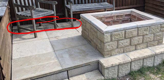
The slabs at the back were a mix of different styles and sizes to just provide a solid base and gap-fill


This project is to build that bench seating.

It will also serve as the new "shed", with a flip top lid where garden tools and such can be stored without needing an actual shed.

The width of the patio between the planters at each end is approximately 12 ft.


While it would have been possible to to get single lengths of timber that would cover the full distance, obviously this would look rather basic. 


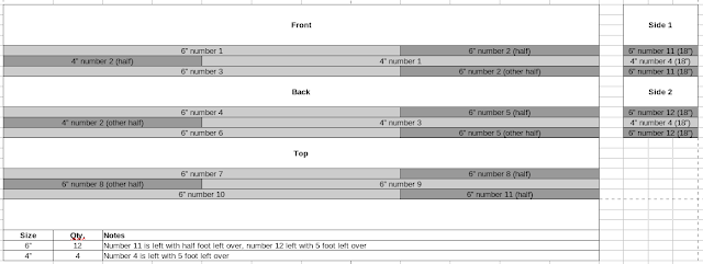
Instead we settled on 8ft lengths which would allow us to create a staggered joint similar to that of brickwork, making a much more aesthetically pleasing finish.

We also opted for 2" thick lengths to prevent warping, and add weight and sturdiness.


The height and depth of the bench are based upon the measurements of existing regular garden benches that we already had, so we can be confident that they provide a good seat height. (~16-18 inches).

This is why the there is a mix of 4" and 6" wide.

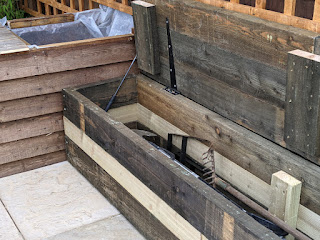
The open lid and gas strut
(before burning)

The remaining lengths of timber were used to create supports on the inside of the bench, where each of the lengths were joined.


The lid/seat was mounted with 3 shed hinges. Obviously a lid of this size is quite heavy, so to aid lifting it, two boot-lid gas struts from a scrap car were mounted, one at each end.


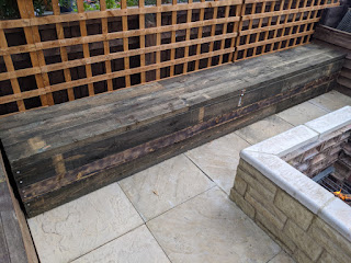
The closed bench, showing the latch
(after burning)

A latch and padlock was also added, recessed into the front (so that it didn't catch peoples legs when sat down.)


Finally there was a colour difference between the 4" and 6" wood - the 4 being much lighter, so it was burned with a blowtorch so that it would fit in better.


Friday, 17 December 2021

Dolce Gusto Genio2 Coffee machine repair

Last year, I was given a Dolce Gusto Genio2 coffee machine for repair.
The owner reported bad water flow, and said that they had attempted to clear limescale, etc using citric acid with no luck, and suspected that the pump was dying.

A quick search showed that there’s an unclogging pin tucked away between the water tank and the machine body. Using that I simply unclogged the nozzle and it worked fine. There’s a good lesson there about trying the simple things before jumping to more complicated conclusions.

Once fixed the owner gave it to me, as they’d already got a new one.

"Before"


Given the wasteful nature of the pod-based machines, and the reputation of the company behind them I took great pleasure in my free coffee machine which I then got some reusable pods for - so despite using one of their machines, I have managed to avoid becoming part of their ecosystem.


The main PCB - the bottom connector leads to...

Recently though the machine broke again a couple of times when turning on the lights would blink several times and then go out - shortly after it would just not turn on at all.

I pulled the machine part. iFixit have a good guide to getting the machine apart, so I won’t rehash that here.

After some testing with the multimeter I narrowed the problem down to to the PCB with the power button and the light on.


... the LED fill level board,
which in turn links to the power button board.


It appears that of the three pins, pin 3 is the power, with pins 1 and two being the return line for the red and green LED respectively.

When picking around with the multimeter some more I accidentally shorted pins 1 and 3 and the machine started up, so it seems that the button shares wires with the lights.

With this information in hand further testing indicated that it was the button itself that was faulty.

Unfortunately, there is not an awful lot of space in case for a replacement button - only approximately 2mm. I did not have a button that would fit, but seeing as I cared more about getting coffee then the aesthetics of the machine, I did the next best thing and drilled the hole through the case running wires to the relevant pins.

Then I attached an external button. One that has an integrated LED back light. It is any a single colour though, so I wired it in place of the green LED, so that the button being lit is indicative of the machines ready state.

Then I put the machine back together, and tested to confirm it works.
It's not the most stylish of alterations, but I had no intention of getting another machine, so it was either this or start getting used to instant coffee again.

After


Thursday, 16 January 2020

Beko WDR7543121W Washer/Dryer Repair


Over the Christmas holidays our Beko Washer Dryer stopped working. It was fine for one cycle, and a couple of days later when we went to do another cycle, it just wouldn’t power on.

After checking the obvious things – fuses, sockets etc, I noticed that when first powered (at the wall), there’d be a faint beep – like the key-press beep, but much quieter.

The machine was pretty new, so the first port of call was see if it would be covered under warranty. It’s about 18 months old, so of course just out of warranty. I tried contacting the retailer anyway to see if there was any room for good will support. Of course there wasn’t – planned obsolescence is their business model, after all.

Some online research seemed to point to the mainboard being dead.
Hoping to get things resolved quickly, I found a replacement board and ordered it.

When it arrived the next day, it seemed slightly different to the original – the part number showed “G09” rather than the “G08” that was already installed. I also noticed that although the board layout was the same, some components were either added or removed.
The original board
 
Reasoning it to be a more up to date and optimised version of the same board, I swapped them out.
Booting it up, it seemed positive to begin with – it beeped, the display lit up, and all seemed well.
Everything seemed to work just fine… until I hit start, and nothing happened.

A local repairman who I spoke to advised me that sometimes these boards require ‘programming’ to work with a machine – which is something even he couldn’t help with, as only the manufacturers’ own contractors are able to do that. Basically, it’s like DRM (digital rights management) for washing machines.
Curiosity got the better of me, so I popped the PCB out of it’s enclosure to take a closer look.

On the other side, there was an Atmel ATMEGA – a family of microcontrollers that I’m quite familiar with. It got me wondering if I could dump the firmware from the old board, find what exactly is needed to get the new one working – my guess would be a serial number or other identifier baked in there that I might be able to transfer across to the new board.

However, when I was researching this board, I found another web page hidden away at WasherHelp. It's for a different model number, but I figured worth a shot.

There was references to a diode on the board that failed – The one labelled D7 on the PCB. I checked on my board, and found that the same diode is dead on my board.

I de-soldered the diode from my board, an SR110 schottky diode, and started looking up alternatives. I found that the 1N4002 diode is similar specification, but is a regular diode, not schottky. This was bumping up on the limits of my electronics knowledge, so I asked a friend who has more professional electronics experience, and he told me it would probably be OK, but would likely run warmer and be less efficient.

I also had an 1N4002 on an old PCB in my junk bin. I swapped it in, gave it a test run, and it worked.

I’m happy that I got this sorted, and hopefully will help others extend the life of their appliances. I’m a little disappointed though that I didn’t get a chance to mess with the microcontroller/firmware stuff though. Perhaps another appliance will give me a chance to explore another time.

Disclaimer: This is just what worked for me, and is in no way professional repair advice or instruction. If you decide to do something similar, remember that you, and you alone, are ultimately responsible for the outcome.


Update December 2022:

In case you were wondering - the fix is still holding up. But that's not why I'm updating.

A commenter asked if I had any higher-res photos of the board to help them fix a burnt out resistor. This is the best I could find:


Wednesday, 2 January 2019

Editing game saves with a Hex Editor

If it wasn't for videogames, I'd probably never have got into the career path I have, and a lot of that also comes from my other habit of taking stuff apart to see how it works.

Back in the days of the original Playstation, I had one of these Xplorer cheat cartridges.

This allowed the use of game cheats that weren't necessarily part of the actual game code.

In addition, the cartridge allowed the user to create new codes, by essentially searching for values in an existing game.

My understanding of it is that it effectively was a memory scanner, that would find values in the systems RAM, and allowed values to be rewritten (constantly rewriting the memory location of the health variable to read 100% would effectively be an infinite health cheat, for example).

Similar application shave been released for PC games, but to be honest, they went to involve running unchecked code and tend to have an air of shadiness about them.

Plus they tend to just be a very directed tool for a specific game title, so blinding running one might help you out with a game, but you're not getting anything useful from it.

This project is to demonstrate that similar results can be produced using standard tools, which have uses beyond games, so while cheating at the game won't make you any good at the game, you might instead learn something that is useful in the real world.

Tools
The tool being used is a Hex Editor (wikipedia). I'm using GHex, but the most commonly known editor is WinHex for windows.

Process

There are several approaches that can be taken, there are some who will painstakingly sit and work out the whole format of the file.

While this is probably the most technically sound approach, it's incredibly time consuming and laborious, particularly if you're only looking to change one or two values.

Another approach is to load a game, make a note of some key values in the game you'd like to amend - ammo, health, cash, etc. The more unique the value, then in theory the easier it will be to find in the file.

For this example we're using Saints Row 3, and in particular we're looking at ammo.

Note that there the process does involve a certain amount of trial and error, so for conciseness I'm not going to cover all of the missteps along the way, just what I did right. Of course it goes without saying making backups of the save before editing is worth doing just in case.

These are the ammo balances of the save I'm using:

The first thing to do is to convert some of these values to hexadecimal so that we know what to look for in the hex editor.

So starting with 265 - this converts to 109 in hex, or in the notation used with most hex editors, this will appear as "01 09", so use the find function in the hex editor to look for all instances of that. There are two likely outcomes, either:
  • You'll find multiple instances, so the next step becomes figuring out which one is the one you want to change.
  • You'll find nothing. In which case the endian ordering of the file could be an issue - this refers to the order in which the bytes are used to create the actual number. In layman's terms, you can think of it as reading from left-to-right or right-to-left. Simply reverse the order of the bytes above - e.g. "01 09" becomes "09 01" and search for that. If you continue to find nothing, it could well be there's some additional encoding or perhaps simple encryption on the file. There's ways around that but it's a bit of of scope for this project - I might do a follow up post later dealing with those things.
As it happened, with the pistol ammo amount I lucked out, there was only the one instance.:

The bytes representing the pistol ammo highlighted in red (click to enlarge)

So, let's change these two bytes to FF (the largest 2-character hexadecimal value - like 99 is in decimal), reload the game, and see what happens.

The pistol ammo is now 65535
(which is the decimal equivalent of hex value FFFF)

So, where to go from here? We can repeat the above exercise with the other values to find them, but we can help to deduce the whereabouts by adding some logic to what we already know - in this instance, we're looking for ammo values, we've found one, and we can reason that it's quite likely that these values will be grouped together.

For example, the SMG ammo value (70 00) was found nearby

The 2 values (pistol value in blue, SMG value in red). Click to enlarge.

From there we can deduce further - The pistol value starts at byte 19104. The SMG value starts at 19132 - 28 bytes apart.

So what if we look forward another 28 bytes at 19160? We find "30 00" - decimal value 48, the value of shotgun ammo. And again, another 28 bytes later we get hex "77 00" - decimal 119, the rifle ammo.


The other ammo values. Click to enlarge

So lets test it and change all of those to "FF FF"
So did it work?


Yes.

SR3 save file 'cheat flag'
Although it's not really in the spirit of this post, if you're here to just cheat at this one particular game, there's a byte in the save file that identifies if cheats were used in the game. It's the byte at 0x000000C8. You can play with cheats, then just change this flag to zero and it'll be as if you hadn't.


A final note on using cheats in games
Using cheats in games is obviously a polarising subject. I am very much opposed to using cheats in multiplayer games where doing so will affect the experience of others.
I am also generally opposed to using them in single player games - whether they're keycodes put in deliberately by the games developers or third party tools that you've just downloaded and ran.
In my opinion you should at least do a playthrough 'as the developers intended', however, they can be a good way of extending the re-playability of the game and getting more life out of your purchase afterwards, and by instead using techniques that I've covered in this post, you can learn and practise techniques that can be useful in the real world, and in my opinion the benefits of that outweigh the drawbacks.

Monday, 5 November 2018

Metro 2033 inspired "Trench" lighter

In Metro 2033 the main character, Artyom, carries a lighter fashioned from a bullet that can be used to light the way in dark areas and burn away obstacles such as cobwebs:


At a local country show I found an army surplus stand selling brass cartridge cases and saw an opportunity to make Artyoms lighter for real.

There is some real world history to this style of lighter. Known as a Trench lighter, items like this were quite common amongst troops in the trenches of the first World War, and relates to a wider concept of "Trench Art".

The case, I'm not sure what it's from.
It's approx .50" diameter at the neck,
but has stamp "SB 13"
 It seems too short to be a
standard .50 calibre round.

So with the case sorted, the next things to consider are:

  • Cap/means of extinguishing the flame
  • Wick
  • Fuelling & refuelling.
  • Ignition
Cap

I wanted to keep the lid of the lighter as a bullet style like in the game, but firearms law and lead content make the idea of using a real one infeasible and undesirable.

Instead I opted to grind the end of a copper bar down to a bullet shape, and hollow the inside slightly to make a cap.
The rounded copper bar.


Creating a hinge for the cap
The next stage is to create a hinge. A copper pipe clip was wrapped around the base of the cap, and secured with Araldite.

A second pipe clip was bent into a 'P' Shape and a bolt used to create the hinge (see gif below)


To attach this to the case, a brass olive from a pipe compression fitting (see pic.) was placed around the neck of the case, and the bottom half of the hinge was squeezed between it can the case to provide a frictional fit for now - it would later be further secured with epoxy.


Part two continues here

Wednesday, 7 February 2018

PC case notification screen

I've mentioned before how my interest in electronics spawned from PC modding.

Now that I've built a new desktop for the first time in a while, I've been keen to return to PC modding and come up with some projects for my new machine.

Thing is, these days PCs are designed much more aesthetically than the old beige boxes, and so there's a lot less that needs doing - the case I have has a large glass window, the motherboard already has some RGB LEDs built in - the graphics card even has some too.

I wanted to add some case lights - thought that might be a nice throwback project, but I noticed the motherboard already has pin headers for a 5050 LED strip. Don't get me wrong, I think it's a good thing that manufacturers are taking the initiative, but all it involved was little more than soldering some wires to a length of LED strip and plugging it in - hardly a project worth writing about.

So I thought about doing a new take on the case-front notification screen. In the past this would be a basic HD44780-type LCD that could display basic text - currently playing track, system temperature etc.
My plan is to use a small, full colour screen to fit with the more colourful style of the new desktop.

Other requirements are that as I dual boot Windows and Linux, it needs to work in both environments, so I'm aiming for minimal overhead on the computer itself.

Setting up the Raspberry Pi

In order to meet that goal, I plan for it to be a completely separate device that the PC can just pipe data to, and the device itself handle the processing and display. I started with a Raspberry Pi A and a clean install of Raspbian ("Stretch Lite"), and booted to the terminal using the serial console GPIO pins.

Getting connected & installing Java
I'll need to get the Pi connected to the internet temporarily to get everything setup and installed. I used a USB wifi adapter then edited

/etc/network/interfaces
 
with the following, replacing the ssid and password as necessary.

auto lo iface lo inet loopback iface eth0 inet dhcp allow-hotplug wlan0 auto wlan0 iface wlan0 inet dhcp wpa-ssid "ssid" wpa-psk "password"

then of course started with the usual update/upgrade

sudo apt-get update sudo apt-get upgrade sudo apt-get install openjdk-8-jdk
 
and reboot if necessary.

The display
As the display is to be mounted in a desktop computer case, there are some rather specific requirements.
  • Size - it needs to be small enough to fit in the case
  • Power - it can't use too much, and needs to be able to be powered from the computers PSU
  • Connectivity - HDMI would probably be overkill, after all, it's for system stats and notifications, not a extra monitor, and it needs to connect to the Pi, so Composite video seems appropriate.

The display and its connections
After examining and ruling out various options - netbook screen, digital photo frame, etc. I came across some reversing camera kits on eBay. For a fairly reasonable price, these kits contain a small camera for the rear of the car, and a small display to view the video on.

It fits the bill nicely - small, composite video connection, and runs of 12v, which can be provided by the PSU. Perfect. The camera the kit includes is unnecessary for this project, but I'm sure I'll find a use for it someday.


Adding a GUI
The Raspbian 'Lite' distribution doesn't come with a GUI, so I needed to install one - I went with RPD.
This is installed with

apt-get install xserver-xorg xinit raspberrypi-ui-mods lxterminal gvfs
 
As the pi will be running without user interaction, it needs to be configured to automatically login to the desktop. This can be done with:

raspi-config
 
We also need it to stop going to screensaver. The easiest way to do this is to just uninstall the screensaver with apt-get remove xscreensaver.
We also need to stop the screen blanking, this can be done by adding the following lines to /home/pi/.config/lxsession/LXDE-pi/autostart
 
@xset s noblank 
@xset s off 
@xset -dpms
 
And finally we need to hide the mouse cursor:

apt-get install unclutter
 
Once installed, we need to add the line unclutter -idle 0 & to /etc/profile.
 
Setting up serial communication
The Pi will be without internet connection, so to get data from the PC to it, we'll be sending it over the GPIO pins.

Firstly, use raspi-config again to disable the serial port console, as this can interfere with the data transfer.

Then run
sudo stty -F /dev/ttyAMA0 speed 115200 cs8 -cstopb -parenb to setup the serial port.

Run the same command on the desktop - just change the /dev/ttyAMA0 part to whatever the serial port on the machine is - most likely /dev/ttyUSB0 if you're using a USB to serial adapter or Arduino. (Currently I'm using an Arduino with a 5v to 3.3v level converter, though will come up with a more permanent solution when installing the screen in the case).

Installing the software
Take the compiled jar and move it over to the Pi - I put it in /home/pi.
Create a file in /home/pi/runPi.sh containing this command

cat /dev/ttyAMA0 | java -jar /home/pi/PiScreen.jar

Edit the /etc/profile and add this command to the bottom

sh /home/pi/runPi.sh &
 
This will cause the software to run on boot, and pipe input to the serial port to the application. That's it for the Pi setup.

Setting up the desktop
The software is designed to take its input from the 'sensors' command which is part of the lx_sensors package, so install this if it's not already installed on your system.

To test the display, with it booted and running, on the desktop send the comman

  sensors > /dev/ttyUSB0

you should see the dial on the display change to show the system temperature.
Send it a couple of times with the system under different loads to see the number change.

To automate this, simply add it to cron to run at set intervals, of if you want it run more frequently, add the below to ~/.bashrc (the 5 indicates 5 second intervals, adjust as necessary)

startSensors() { while true ; do sensors > /dev/ttyUSB0 2>/dev/null & sleep 5; done } 

This will allow the sensors to be started by using the command "startSensors &" in a terminal.

The next steps will be tidying up the wiring, and mounting it in the case itself.


The UI is quite basic at the moment, but I intend to expand on it to include other stats and publish the source so that others can add their own widgets to the display.

Monday, 4 September 2017

LAN-party in a box, part 3

Part 3: The software side
Finally got round to tidying up the code. There's the arduino sketch which powers the lights, and a java application that runs in the background on the server, reads the server logs and will produce the serial commands that are sent to the arduino.

It uses the RXTX serial library, and the code itself is available on GitHub at https://github.com/darkmidnight/UnrealLANBox

There's still room for plenty of improvement, like getting the lights to flash when a flag has been taken.

I also put together a video showing the build process and a demo of it in action, see below