Showing posts with label Arduino. Show all posts

Saturday, 10 June 2023

Treadmill Videogame Controller part 2

Since building the treadmill project late last year, I did actually manage to complete a full run through of the original Sonic the Hedgehog.

Along the way I found a few snags and issues with the treadmill:

Direction switch/lever

I soon found that the reed switch control from the cross trainer levers was problematic because there was a lack of tactile feedback to know when the lever was in the correct position for changing direction.

Therefore, I replaced it with a regular switch where normally open connected the ‘right’ key and the normally closed connected to the left key. Using a metal angle bracket I was able to mount it to the frame so that the switch is closed when the lever is fully forward, and open in any other position.

This means that when moving right I just need to keep the lever fully forward, and to change direction I just have to move it from that position.

Although I kept them in place for the duration of the Sonic play-through, I’ve since removed the cross trainer levers, as they do not provide any real benefit over a regular button.
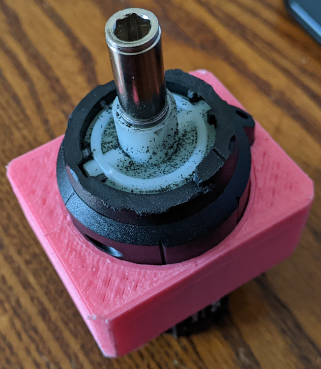
Jump button

The large plastic button that I was using as a jump key broke (it was from a cheap “noise-maker” type toy, and the PCB literally snapped), so that was also replaced with a basic switch. I plan to change this up for something better in the future, but at the time I just wanted to go for a run.

Quick save and quick load 

I found, particularly on the more platform/puzzle sections of the game, it became necessary to make use of the quick save and quick load features of the emulator, so I added an external quick load button to the treadmills handlebar.

A better button system

All of the above can be distilled to a single point - that the button inputs were not good enough.

Although I started the project with the intention of minimising the number of regular button presses, it seems inevitable that there will always be some required.

Configuring the controls

In order to play other games I would need to make some additional adjustments for different control schemes. This would mean altering the firmware and re-uploading every single time I changed the game, which seemed needlessly convoluted.

There were two main reasons for using the Makey Makey. The first was to take advantage of its noise filtering features, and the second was its ability to act as a keyboard.

The noise filtering is the real selling point of using it, but there are other ways to obtain its input and then turn into keyboard input. So I adapted the firmware so that instead of sending keyboard input it would appear to the connected computer as a serial port. On each cycle it would send one byte, with each bit representing the button state (i.e. pressed or released) of each of the buttons.

This would allow a data transfer rate fast enough to handle pretty much any input I can throw at it.

The source code for this can be found at Github.

The software

The software will be an ongoing development project so I’m not going to be sharing it at the moment.

On the computer side, an application will continuously read the serial import, and then translate it into appropriate keyboard events via udev, thereby sending whatever that keyboard input is to ever application is active and in focus on the computer – in the case of this project that will be a game.

For this iteration of the treadmill I’m going to be using the acclaimed indie game Super Meat Boy – as it has a small range of inputs (left, right, sprint and jump) but adds a couple of extra bits of complexity for me to expand on with the treadmill.

Once the serial connection is established, a thread runs constantly, reading the latest byte from the Makey Makey.

It compares the byte to the previously read byte. If a bit that wasn’t previously set is now set, then a corresponding function is called in a secondary thread, which is the input thread.

The input thread maintains a count of “presses” from the treadmill rotations, which increases with each press as well as decreasing with the passing of the specified time interval (the “decay”).

If the count is positive then the first key (the direction) is pressed.

If the count is positive and greater than the defined sprint threshold then the sprint (shift) key is also pressed.

For the jump key, the serial thread will always report the state of the relevant bit to the input thread.

This compares a pair of booleans (jumping and lastJump) – which determines whether the jump (space) key should be pressed or released. It is done this way because Super Meat Boy differentiates between small and large jumps based upon the duration of the key press.

Saturday, 4 March 2023

Modernising the electronics of a vintage Singer 99k sewing machine

As I mentioned in my previous post when I was restoring the sewing machine, the electronics were in a pretty bad state.


I believe the pedal was meant to allow for variable speed input, but in reality it acted just like a simple on/off switch, and pressing the pedal down the whole way tripped the circuit breaker.

Inside the motor housing once
the rotor had been removed.

Initially I tried just repairing what was there, replacing brushes in the motor, cleaning it all up – which seemed to provide some temporary improvement but it soon deteriorated again.


So I decided to just try and replace all of the electronics with modern equipment, but retained the original casings to try and maintain the rustic aesthetic. I figured with modern advances in electronics it is quite likely that a lower power, modern motor would be able to provide comparable performance to the old one (the analogy that springs to mind is the state of modern cordless power tools versus old mains powered ones).

It is clear that the original motor does not have any kind of gearing to boost power – the circuit seemed to be about as basic and simple as it gets.

As I was researching the old motors I did see some mention about potential asbestos hazards – this is near the bushings of the motor – it is intended to support the bushing and act like a self-centering bearing. As I am entirely replacing the motor I had no need for it. With appropriate protective equipment in place I was able to remove it and dispose of it appropriately.

There was also mention about the being asbestos washers in the foot pedal, however my one does not appear to have these – but nonetheless I will not be using this pedal anyway.

One side the case of the me to opened up I was able to pull out the coil windings and rotor, leaving an empty shell. I removed the original connectors.


The screwdriver
To replace the motor I am going to use a cheap cordless screwdriver. Being cordless it should be adaptable to run on a lower power, but given the task that it is designed for, it should still be able to provide enough torque to run the machine due to it’s gearing set up.

In these cordless screwdrivers all the electronics tends to be in the handle, so it is easy to separate out the motor and gearing system from the rest of the device.


With that done I needed to trim off some of the casing to get it to a suitable size to fit in the sewing machine motor case. 

The screwdriver in it's mount

The only modification I needed to make to the sewing machines motor case was to drill out the opening slightly as the shaft of the screwdriver was a little bit wider, however this is not actually visible from the exterior.


To mount the screwdriver, I 3D printed a mount (Github/Thingiverse).

It's simply a friction-fit wedge that goes around the screwdriver body and into the sewing machines original metal case. 

The diameter of the shaft of the motor is the same as the original motors pulley, but worth bearing in mind that the new motor is slower. I had the idea to increase the diameter of the shaft, in order to change the gearing between the motor and the sewing machine and get a bit of a speed increase. It should also increase the grip on the pulley as there will be a larger surface area of the belt in contact with the shaft.


To do this I created this (Github/Thingiverse). It fits within a small section of aluminium tube (to prevent wear on the plastic), and over the shaft of the screwdriver. It's locked in place with an allen key (cut flush) that fits as if it were a screwdriver bit and locks into this plastic widget. Finally I locked it all together with some adhesive and wrapped a bit of grip-tape around the aluminium. 


Driving and control
To drive a motor I am using a BTS7960 motor driver, controlled by an Arduino (for now, for the purposes of prototyping).


Simply this will be an analog input, which the arduino will translate into pulse width modulation (PWM) and send to the motor driver. This is possibly overkill, but the priority at the moment is too get the machine working – optimization & improvements can come later.

For now, I have a simple potentiometer to set the PWM, and the pedal is actually just a switch cable tied to the legs of the sewing machine. I am hoping to be able to get a treadle foot pedal like those that would have traditionally been part of the table legs that I’m using, and use that – if I’m ever able to find one.


Pulley Belt
The belt connecting the motor to the machine was worn through and hanging on by a thread, so it needed replacing.

There seems to be a lot of various DIY how-to ways suggested to create pulley belts to size, so I started working through those. The results were:

  • Pulley belt from an old printer cut to size and stitched together using fishing wire - failed - snapped.
  • As above, but joined with glue and stitched - snapped.
  • Electrical wire (speaker cable) threaded together, and heat-shrunk to provide a rubberised grip. This seemed promising - it didn't snap at least, but the heat shrink, although intended to provide grip, seemed to have the opposite effect.

After all that, as a temporary measure, I joined 3 nylon cable ties together, just so I could move on to the rest of the project. And as the saying goes "There's nothing more permanent than a temporary fix", it's still going strong.


Light
The motor housing also contained a small lamp fitting. This was previously a mains powered, incandescent, bayonet fitting bulb. However I rewired and replaced this with a 12v LED bulb – much in the same way the I did with the Sunset Sarsaparilla lamp project.


Power
Power was provided by an old desktop computer power supply. This provides 12v lines for driving the motor and the light, and 5v for the logic. Again, this is another quick prototyping move, and will eventually be replaced by something nicer.

Finally all that was left was to oil the machine as indicated in the original manual, and give it a try.


Thursday, 15 December 2022

Slack/Whatsapp controlled colour-changing and morse code Christmas lights

Several years ago I made some Christmas lights that could be controlled via Slack and WhatsApp, and every year since I find that I need to update the interface to these platforms to account for the changes that they make during the year. 

Usability updates

This year whilst I was doing that, I took the opportunity to add a few new features and simplify the interface.

Now it responds to some key words – all, top, bottom, half, alternate, led, and allows the user to specify certain colours by word and all colours by hex code.

Additionally I refined the serial interface to speed things up.

Moving to a single-board computer

 
For my home implementation of this, previously I would just run a USB extension lead from my desktop. 


I have now migrated the code to a PCDuino2 single board computer. This is a 1Ghz Allwinner A10 chip SBC, which also contains Arduino pin headers.


The board is discontinued (I bought this one from Maplin years ago during their closing down sale), and as a result there is little in the way of official repositories or archives for the Ubuntu variant distribution that it runs. Plus it looks like there’s some sketchiness around the official firmwares around the allwinner chip that powers it.


I found a version of Armbian linux for this platform and burnt it to a micro SD card.
This allowed me to get the PCDuino to boot to Armbian.


Unfortunately it looks like there is no real support for installing Armbian to the NAND storage which is on the PCDuino. However, leaving it on the micro SD has some advantages such as easily being able to image and back up the install.


Then it was simply a case of connecting it to the network and updating it, enabling SSHD for ease of maintenance going forward, and installing required tools for the Christmas lights server (JDK and Arduino).


As the PCDuino is not a typical Arduino development board it needs its own board definition to be used with the Arduino IDE, so for now I decided to continue using an externally connected Arduino.


Implementing morse code

 
One of the downsides to the set up the I currently have is that the serial data transmission can be disrupted by the update process transferring data from the Arduino to the lights.


The changes I have made reduce the amount of data that is transmitted via serial and so minimize the problem.


However there is additional functionality that I wish to add that will require further data to be transmitted – that is to have a set of lights which flash similarly to regular Christmas lights, but instead of a standard or random pattern, they blink out morse code, based on a message input from the control application.


Rather than cram more functionality into the WS2812 lights that I am currently using, I plan to leave them be and use a regular set of plain white fairy lights for this. Typically I have always decorated our Christmas trees with a multi colours set and a plain white set, so this fits with what I would typically do anyway.

The lights I used are powered from 3xAA batteries (4.5v), which can easily be substituted for USB and powered from a USB hub. To toggle their on and off state, I have used an optocoupler which will be toggled from the PCDuinos GPIO pins.


The ‘arduino-style’ pins of the PCDuino board can be reached in be linux file system via GPIO – similar to the way I toggled an output pin on the frequency switch project.


Seeing is this makes it quite easy to simply toggle a pin on and off, I should be able to use this for the morse code without having to depend on the rather outdated and no longer supported PCDuino board definitions.

Finding the pin reference

 
A ‘gotcha’ about using the sysfs GPIO interface is that the pin numbers as they may have silk screened on the board do not necessarily correlate to the pin numbers in the file system.


The first thing to do is figure out what the pin identifier would be. In this instance, I found some config files for the PCDuino on GitHub.


There lists the PCDuinos GPIO pins and there corresponding identifier, summarised below.

GPIO PinPin ID
0PI19
1PI18
2PH07
3PH06
4PH08
5PB02
6PI03
7PH09
8PH10
9PH05
10PI10
11PI12
12PI13
13PI11
14PH11
15PH12
16PH13
17PH14
18PH15
19PH16

I’d decided to use GPIO 8, so the relevant ID is H10

The Sunxi wiki demonstrates how to calculate the relevant GPIO number from that ID

(position of letter in alphabet - 1) * 32 + pin number

so with H10, H is the 8th letter so

(8-1)*32 + 10 = 234


So with that number calculated, we can export the pin with

echo 234 > /sys/class/gpio/export

which will make ‘gpio234’ available under /sys/class/gpio.

From there we can make it an output, and change the ownership so of it’s value file so that a regular user can write to it.

echo out > /sys/class/gpio/gpio234/direction

chown -R ant:ant /sys/class/gpio/gpio234/value


Then to switch the lights on,

echo 1 > /sys/class/gpio/gpio234/value

and

echo 0 > /sys/class/gpio/gpio234/value

to turn them off


A demo video is below, and as usual the source is available on GitHub.

Merry Christmas!


Saturday, 15 October 2022

Treadmill Videogame Controller

Like a lot of people, I spend a lot of time trying to balance the need for exercise and fitness with the desire to sit on the couch and play video games.

So I figured why not combine the two.

To start with I picked up a treadmill – this one is a manual treadmill as I want its movement to be dictated by my running, not by some electric motor.

There is a small control panel on the treadmill which provides some statistics. It is completely optional and not required to use the treadmill. It gets it’s power from a separate battery supply.

Although this is not particularly useful to me, it does indicate there is some type of encoder in the treadmill assembly to measure these values. Before even taking the treadmill part I can surmise that this is most likely either a magnet and reed switch assembly, a hall effect sensor, or a rotary encoder.

Once I got the treadmill, I could see a simple 2-wire lead from the base of the unit through to the control panel, connected with a 3.5mm jack.

I breadboarded a small breakout so that I could connect the oscilloscope and see what kind of signal was being passed.


This revealed that there’s 2.5v being sent down the line (tip of jack is positive), and that the signal would transition between high and low as the treadmill was used, and the frequency would increase as the speed increases.

In it’s most basic form, if we can translate those state transitions to key presses, that should work.

There was however a whole lot of noise in the signal which seemed to be caused by resonance in the treadmill frame, as there would be severe jumps simply by my touching it.

Initial Implementation

An initial attempt to use an Arduino and have the signal trigger interrupts wasn’t successful due to the noise, and filtering attempts became quickly time consuming.

The requirement for the filtering and the requirement for it to be an input device led me to a MakeyMakey development board.

This board is advertised as an educational toy, that allows users to turn anything into a key. In order to do this it provides a significant amount of signal processing and filtering. So in other words, exactly what I’m looking for.

This means that very little is required on the software side, as the Makey Makey presents inputs to the computer the same as a keyboard would, and applications generally will not notice any difference.

By simply connecting a crocodile clip from the tip of the 3.5mm jack to an ‘key’ on the Makey Makey, and connecting the body of the jack to the ground of it, that is already enough to get some response. Every pulse sent by the treadmill gets interpreted as a key press and release by the Makey Makey.

Problems

The only problem with that is with the treadmill in normal operation, the pulses (and therefore keypresses) are so quick that they do not translate real world movement into equivalent in-game movement.

With the treadmill running, the red marks show the time that the key is pressed. The two ‘bursts’ of movement on the treadmill appear as a total of 14 short keypresses.


Instead, either the rapid tap causes the character to barely move, or if the treadmill stops when the signal is high, the character runs at full speed without needing any further movement on the treadmill.


The treadmill stopped when the signal is high – making it look like the key is held down indefinitely, even though the user is not running


What I want to do is to bring the game input more “in step” (ha) with the movement of the treadmill, so that the same two bursts of treadmill movement would look more like the following:


The two bursts of activity are represented as two longer keypresses, as if the key were held down for the time the treadmill is moving

To do this, I forked the source repository of the Makey Makey project, and made some edits.

The changes are mostly in the updateInputStates function, and focus on the ‘right’ key on the Makey Makey, as I will be using a side-scroller game to test.

Demo

To demonstrate what this change does, below are two screenshots which represent a few seconds of continuous running on the treadmill.
The first is with the treadmill connected to the “Up” key, which is unaffected by the code changes. The input is shown as repeated press and release events.
The second is with the treadmill connected to the “Right” key, which is the one that I have changed.
The impact is shown any as press events, up until the point that the treadmill stops. This is the same as if the key were held down.

The test code is based on KeyEventDemo – the only change is that I removed the KeyTyped event as it is not relevant to this exercise.

Implementation 

Unfortunately there is no way of determining the treadmills direction of travel as it was obviously not designed for that, but in a game I may want to change direction.

What I have done is a workaround for now is I have made the same change for the left key as I did for the right and have wired the treadmill to the Makey Makey like so:

This means by simply flicking the switch I can change direction. In a subsequent moment of inspiration I swapped the switch for a pair of reed switches and a magnet attached to one of the cross-fit handlebars that are on the treadmill - allowing for the direction to be controlled with the left lever.

I have also wired a simple momentary switch to the space key to allow my character to jump.

For now this whole contraption is held together by screw terminals and crocodile clips as it is only a prototype and is a platform I want to expand on in future.

The Game

For this initial experiment I wanted to use a game where input is limited, as a proof of concept.

To keep with the theme of running and speed Sonic the Hedgehog seemed like a suitable choice.

I will be running this on a PC with a Sega Genesis/Mega Drive emulator.

Please note the various copyright and legal complexities around the use of emulators and ROMs - the short version is that you should not use ROMs of games you don't own.

I actually own two copies of the game - an original Mega Drive cartridge, and a PC version as part of the "Sega Mega Collection Plus". It's just that the Mega Drive emulated ROM is easier to interface with.

The end result:


Wednesday, 20 April 2022

Motion activated and timed staircase lights

Years ago, when I first started with electronics one of the first projects I did was to create some motion-activated lighting on the staircase.

It was a basic setup with stick-on LED lights, activated by a pressure pad under the carpet on the top and bottom step. This is a re-make and update of that project in my new home.


The lights

I recovered 6 under-counter lights from a kitchen renovation.

The fittings are for G4 bulbs, run off 12V AC, and have a nice chromed finish.

The bulbs were originally halogen, but I swapped them out for LEDs to reduce the power requirements.

As the lights are designed for AC voltage, they can also be driven by a DC supply to simplify the circuitry and make it easier for them to be micro-controlled, so in effect they will be little different to regular LEDs.

The staircase doubles back on itself, so the idea is to mount the lights in the middle partition, and then run the wiring to the control in the under-stairs cupboard. 

Because of the number of steps on the staircase, there will be one light every two steps starting at the second step.

This will put two lights on the bottom half of the stairs, one light on the middle landing, and then 3 on the larger upper half of the stands (as there are more steps on that half).

Routing the cabling

The main difficulty will be in routing the cable for the lights on the upper part of the staircase as it will be difficult to recess the lights without the cable needing to be threaded all the way through. Rather than run the cable all the way through, then have to recess it I opted for a method using the drill as illustrated in the graphic below - this minimizes the amount of material that was removed from the sides and reduces the amount of patching and filler that is required. 

The sensors 

To modernize the switching system, I am implementing a sensor system at the top and bottom of the staircase. I originally intended to use passive infra-red (PIR) sensors, however I don’t want the lights to be triggered just walking past the staircase, and these can be tricky to focus on a precise area.

Instead I’ve opted for ultrasonic distance sensors - not just like the ones used as car parking sensors, but literally those.

These systems typically contain four sensors, a control box, and a small LED display module.

There are several others who've made efforts to interpret the pulsed signal from the control box. I initially tried to follow a similar approach with mine, however was unable to get the example code working - it seems perhaps the sensors I have were either using a different PWM speed or encoding system.

As I do not care too much about measuring the exact difference, and am treating them more like a 'beam-break' sensor, I can take a rougher approach to detecting motion.


After some prodding with an oscilloscope I found a couple of pins that showed a square waveform that appeared to react suitably to me waving my hand in front of the sensors.

I put together a simple arduino sketch to read the rising and falling edge of those waveforms, and simply counted the transitions.

This is a rather effective, but admittedly hacky, solution - basically just observe the range that the transitions are when there's no obstruction in front of the sensor, what the value is when the sensor detects something, and then simply if/else on the value to detect if the sensor has been triggered.

Lighting Pattern and Timing

The lights will be patterned to switch one at a time, starting at either the bottom or top of the stairs (depending on which sensor is triggered), remain on for approximately 10 seconds, and then switch off in the same order. 

The Circuit


The Code

As usual, the code is available on GitHub.


Monday, 21 December 2020

Slack & WhatsApp controlled Christmas Tree Lights

December 2022 update: I've developed this idea further, giving the project more features, including the ability to blink lights in morse code. The original post remains below.

With the Covid-19 pandemic still dragging on, it looks like things won't be back to normal in time for Christmas.

At work there was discussion about Christmas parties, team building exercises, and other such things to try to boost morale.

I'm currently working on a project that uses WS2812 RGB LEDs (which'll no doubt wind up published here eventually), and on a whim, wondered if there existed fairy lights that use the same chip.

Turns out, there are. So obviously I had to buy some.

My Christmas tree is positioned so that is can be seen in the background when I'm on Zoom calls with work, so I thought it'd be fun if I could setup some system that would let my colleagues interact with the lights.

Once the lights arrived and I'd tested them, I got to tearing them down.

Wiring

The power supply/controller is a USB unit. I was powering it from a phone charger adapter. That also contained an infra-red receiver for the included remote. I thought about potentially working that angle, but the remote had limited options, and I wanted to offer more granular control.

From the controller to the lights was just 3 leads, which I rationalised must be +5V, Ground, and Data.

I cut the wire, figured out which was which, and connected in an Arduino. It wasn't able to provide enough current to drive the LEDs itself, to I made use of the existing charger - the charger continued to be connected to +5V and Ground, sharing the ground with the arduino's ground, and then the data line connected to the arduino.

The circuit. It works fine like this for short periods, although I later found adding a 470 Ohm resistor between arduino D12 and the first LED increased reliability over time.


Arduino code

I ended up using the PololuLedStrip library, and modifying the existing code for that.

Initially I'd hoped to be able to provide full RGB control, but it just seemed that the sheer amount of data being sent meant bytes were being lost, or I had to slow the data rate down to unusually slow.

Eventually I settled on using 10 preset colours, defined with numbers 0-9, being sent as a 100-character serial string - 1 character (colour) per LED. This seemed to be the best trade off of functionality and reliability.

The code can be found here.


The 'server'

This is a simple web server that accepts GET requests for one endpoint, and is simply there to provide a go-between for the messaging apps and the serial port.

As each LED is individually addressable, I wanted to create a format that would give users control at that level. I settled on messages with the following JSON structure

[1,"colour"]

or

[[1,2,3], "colour"]

where the numbers are the IDs of the LEDs, and the string is one of the available colours.

This would let them control either an individual LED or a series of them in an individual command.

Hooking into Slack and WhatsApp

As at work we use Slack, and we have some previous integration with it, it seemed like the obvious choice.

However, their API functionality is heavily focused on HTTP endpoints, and requires a server to interface with it. That's fine for 'proper' development, but when I'm just messing around at home, I don't really want to be dealing with opening up my home network and all that entails.

Really what I wanted was some client-side plugin functionality. There isn't an official API or interface for one, so I had to improvise.

Using the web-browser interface, and making use of Firefox's Javascript console, I added a MutationObserver to the page, and made use of the DOM to narrow in on the message elements, and get the contents of the latest message in whatever chat/channel the user was in.

The javascript for Slack can be found here.

Once retrieved, some basic checks are done to make sure that the message is in a usable format and hasn't been acted upon already, it's then passed to a local server via HTTP, where it's processed, converted to the serial format used by the arduino, and sent onward to it.

After realising how useful MutationObserver is for things like this, it was quite trivial to do the same for WhatsApp.

The finished product


Thursday, 10 December 2020

Live-edge oak spotlight light fixture - part 2 - adding ambience

In my previous post, I built a hanging light fitting of live-edge oak and recessed GU10 spotlights.

There is actually more to the project.

Sometimes, spotlights can be a bit overpowering, and it's preferable to have some ambient, indirect light.

During construction, I had the idea of creating this light in a way that would allow use of the spotlights, an ambient light, or both.

To create the ambient light, I used LED strips on the reverse (upward-facing) side, to reflect light off the ceiling.

I cut some thin strips of oak with a 45-degree angle and mounted them in a rectangle on the back - angled side outward, to help direct the light. An RGB LED strip was mounted all around this.

Control

I initially thought of using the LED driver that tends to come standard with rolls of LED strip, but as the existing wiring leads to only one switch, without some rewiring through the ceilings/walls, it would be limited to either having both the spotlights and the ambient light on, or just the spotlights on without the ambient light - it would not be possible to have the ambient light on without the spotlights.

In order to combat this, and to lay groundwork for a potential future project, I included a solid-state relay and an Arduino. The arduino would drive TIP31 transistors to drive the 3 channels for the LEDs red, green and blue, and additionally control a solid state relay which would act as the switch for the spotlights.

The idea would then be that the light switch would remain on, more like a utility switch, and then all control of the light fitting would be handed over to the Arduino.


Power


The original wiring sketch.
it's just a rough sketch,
not a proper wiring diagram.
 
The LED strips take 12V, and the microcontroller takes 5V, so a PSU is needed to bring the power down to usable levels.

For this I used an old net-book power supply. This was wired into the back of the light fitting. Caution is needed to make sure that nothing too powerful is used, as typically a houses' lighting circuit breaker is tripped at a much lower current than the mains sockets.


Revised to include the additional components
This would normally be plugged into a wall socket, where it's plug would have a fuse. However in order to wire this into the lighting wiring, the plug would need to be removed - obviously this introduces a safety concern. To ensure that this would still be fused, I replaced the wall switch for the light to one that includes a fuse, ensuring that the light is behind the fuse.


Communication

To communicate with the Arduino, I used a cheap HC-05 bluetooth to serial adapter, the same as I've used in other projects like the Bluetooth Macro keyboard app.

The arduino receives 4 bytes, followed by newline characters. These correspond to 1 byte each for the red, green and blue channels in the LED strip, and the final byte is either a simple 0 or 1 to indicate if the spotlights should be on.

For now this is sent by pairing with my phone and using a bluetooth serial terminal app from the Google play store. I'll probably create a more custom app in future, but for proving the concept, this works just fine.