Showing posts with label handmade. Show all posts

Tuesday, 30 May 2023

Wheeled flower pot stand

When I started woodworking, a key motivator was simply financial - make stuff myself and save cash.

A recent trip to the garden centre, where they were selling these wheeled flower pot stands at absurd prices, convinced me to get back to basics and make my own.

There's nothing complex about this build. Simple pallet wood - all from the same pallet to keep consistent appearance, and avoid the need to process the wood too much (planing, thicknessing etc)

A simple grid of five slats with gaps in between and two perpendicular underneath, all 40cm in length. Each overlap with two screws - the only 'gotcha' being to be mindful of the screw placement on the end ones, given that it'll be cut into a circle.


Then simply cut into a circle with a jigsaw, and a quick sand to remove sharp edges.

Four wheels from an old office chair were attached - these are simply push-fit into a drilled hole.

That's all it took - literal junk (pallet wood, wheels scavenged from a binned chair, and even the screws were from the 'miscellaneous' jar). Whole thing took less than a couple hours and saved about thirty quid.


Tuesday, 11 April 2023

“Picture and Collection Bar”

This is another one of those projects I found on Pinterest & decided to make a DIY implementation of. The original pin describes it as a “picture and collection bar”.

Essentially using a wooden strip to trap marbles in such a way that they have a little movement but due to the sloped design will always try to move downward and towards the wall.

This means that if you push a piece of paper through the gap at the bottom, there is enough movement for the marbles to get out of its way but they will immediately roll down, providing just enough friction to hold the paper – but not enough friction to prevent you from easily removing the paper again if you need to.

It’s kind of like an ultra slim pin board, but without having to put holes in your paper.


Design
The original design I found used pretty thin strips that appear to be jointed it mitred angles.

Instead I opted for using a larger piece of oak, but then cutting out an angled gap for the marbles.

The cross section looks something like this:

Construction
The actual construction of this was very simple, just a series of rebate cuts on the table saw, occasionally making one of them angled, and making one very us at the bottom of the piece, so that when it’s up against the wall there is a slight gap as can be seen in the above diagram, which will allow paper to pass through.

Then I capped off the ends with a little piece of mahogany, to prevent the marbles from rolling out the sides – this is simply glued and pinned in place – and then finally some finishing.

As the piece of oak I was using was reclaimed and had a couple of screw holes, I patched one which looks a little bit like a knot in the wood, and the other two which were at the edges, I decided to patch using brass tacks, as the holes were in a position where if I were going to screw this to the wall I would have put holes anyway.

Mounting
The tricky part of this project is mounting it to the wall. My design does not have a back piece because I did not want it to protrude too far from the wall. The downside of this means until it is on the wall, the marbles could fall out the back.

So, firstly, I filled the back with some marbles.

 I then used gaffer tape across the back of the marbles and the lower part of the bar – leaving the side top bit exposed as this is where the adhesive is going to go. I left enough excess gaffer tape to be able to fold it round so that there was a ‘handle’ hanging off the bottom of the bar.

Obviously the next step is to mark out a position on the wall to mount it, make sure that it is level, etc. Then apply the glue to the back of the bar, and stick it to the wall.

Once you’re confident that the glue set, you can put on the gaffer tape ‘handle’, to peel the tape away from the marbles on the back, releasing them.


Result


Tuesday, 9 August 2022

Multi-tiered triangular planter

I'm pretty sure at some point I said I was done with making planters, but, here we are, here's another.

It's a multi-tiered, 4-segment planter made from pallet wood and arris rails from a dismantled fence.

I've always liked the idea of mixing differing heights in gardens, like with the firepit project, and as we're aiming for a zero(ish) waste approach to the garden, planters are a great means of re-homing soil that is displaced from other projects.

The triangular arris rail is an example of letting the available materials influence the design of the project. In my original sketches I'd planned for a square design, but finding the arris rail led me to using triangles, which actually fits better as the planter is intended to go in a corner.

Likewise, the pallet wood influenced the sizing, as the sizes of the triangle are 120cm, which is a standard footprint for a pallet.

Sunday, 27 February 2022

Flip-top bench for garden storage

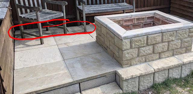
Building on from the last fire-pit/patio project, the reason that I was not too worried about the mismatched slabs at the back of the firepit patio was because I knew that the aim was to put some bench seating there which would cover them over.

The slabs at the back were a mix of different styles and sizes to just provide a solid base and gap-fill


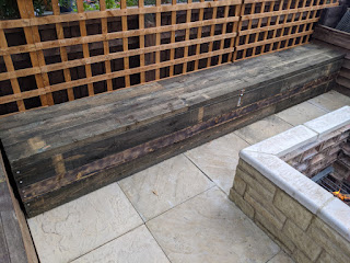
This project is to build that bench seating.

It will also serve as the new "shed", with a flip top lid where garden tools and such can be stored without needing an actual shed.

The width of the patio between the planters at each end is approximately 12 ft.


While it would have been possible to to get single lengths of timber that would cover the full distance, obviously this would look rather basic. 


Instead we settled on 8ft lengths which would allow us to create a staggered joint similar to that of brickwork, making a much more aesthetically pleasing finish.

We also opted for 2" thick lengths to prevent warping, and add weight and sturdiness.


The height and depth of the bench are based upon the measurements of existing regular garden benches that we already had, so we can be confident that they provide a good seat height. (~16-18 inches).

This is why the there is a mix of 4" and 6" wide.

The open lid and gas strut
(before burning)

The remaining lengths of timber were used to create supports on the inside of the bench, where each of the lengths were joined.


The lid/seat was mounted with 3 shed hinges. Obviously a lid of this size is quite heavy, so to aid lifting it, two boot-lid gas struts from a scrap car were mounted, one at each end.


The closed bench, showing the latch
(after burning)

A latch and padlock was also added, recessed into the front (so that it didn't catch peoples legs when sat down.)


Finally there was a colour difference between the 4" and 6" wood - the 4 being much lighter, so it was burned with a blowtorch so that it would fit in better.


Sunday, 15 August 2021

Planter from old shed

When working on the patio and fire pit, I took on the challenge of 'zero-ish' waste - not having any more waste than could fit in the regular household bins. No skips, special collections etc.

On the opposite side to where the fire pit was built, there was an old shed, which wasn't in bad condition, but was unwanted.

It was taken down so that we could make use of the paving slabs which were being used as it's base.


Along the side of where the raised patio was being built, there was a gap which used to have long-dead roses in - the area marked in brown in the patio-plan model below


Just eye-balling it, I could see that the length of the shed (approx 8 feet), was about the same, and came up with the idea of using the sides to create a raised planter there. 

It also helped the zero-ish waste plan, as the planter would provide space for re-homing soil removed during the fire pit and patio builds, as it could be filled up from ground-level

The frame was simple, just the four sides simply screwed together - leaving the bottom open for drainage.

The front panel was cut down from the front of the shed (below the windows), and the back of the planter was one of the roof panels of the shed. The sides were the other roof panel, cut lengthways.


The back of the planter is higher than the front - I considered cutting it down, but it does provide some utility in that it gives a place to mount things like chicken wire/frost protection/cold frames over the top of the plants if need be, and as it is still lower than the fence itself, I decided to leave it alone.

And finally some miscellaneous bits of shed timber was used to add trim to the top of the panels, which also served to pin the plastic liner in place.

The wood was treated with normal fence stain/wood preservative.

The insides of the frame are lined with plastic sheet (which as it happens, is also up-cycled from some packaging.) and stood on some slab offcuts to protect the wood from moisture caused by contact with the wet soil.


Tuesday, 15 June 2021

Workshop apron from leather scraps

Now that I've recently added a welder to my workshop, I need something a bit more protective than just the usual old clothes I use as workshop attire, so I've been planning to build a leather apron.

What makes this project a bit different though, is I have inherited a large box of leather from another leather crafter who sadly passed away. It's a significant amount of material, so I don't really want to go purchasing yet more for this project.

So the challenge that I set myself is to 'frankenstein' the apron together from the smaller pieces, but do so in a way that hides that fact - or at the very least, styles it out so it doesn't look like a patchwork bodge.

I'm using a borrowed canvas apron as a rough template, but will adapt where necessary to suit me.

The largest suitable piece I have is this, which covers most of the area, but the template comes in a bit short at the edges.


A second piece, although a different colour can attach to the bottom, extending it to a more suitable length. This covers the size of the canvas example apron.


I also created edge pieces for the vertical sides of the apron, to tidy it up.
When I've used aprons in the past, I've always found an annoyance of them is how the side bits often 'flap about'. To try and combat this in this design, I've enclosed a length of steel wire in there, which should strike a balance of being flexible enough yet maintaining some sense of shape.


There's still the scuffed portion at the top to deal with. This will be where I affix the straps, so have cut a couple smaller pieces of thicker leather here so which cover the problematic patch, and provide the mounting point for the strap. I did the same on both sides to maintain the symmetry.

There was also enough left over to add a central pocket, which I planned to divide into two.


 I wanted all the pieces to be a consistent colour, but not too dark, so I opted for a shade of brown just slightly darker than the pieces were currently.

After dyeing, I fixed the bottom and side sections in place with contact adhesive. This would serve as a placeholder while I stitched them, and add to the overall strength.


Straps

In the box of leather that I inherited, there were what appear to be, a number of several unfinished belts. These were all consistent in the type of leather, so were perfect to repurpose as straps for the apron. All I needed do is dye them to match the colour.


For the shoulder straps I used a single rivet, as this would also act like a pivot and allow flexibility. This was covered over by the top pieces I mentioned earlier.

I joined these in the middle of the back using a small piece cut from thick leather, from which another piece moves downward to join the belt portion, like a 'Y' shape.


Another 'junction' piece joins that to the belt in an 'upside-down T' shape.

The belt itself is simply riveted to the sides of the apron. I made the right-hand side particularly for the buckle, as I reasoned it would be easier to fasten/unfasten from the side of the body than trying to reach behind my back.


Finishing touches

I soon realised that the front pocket would just end up filling with dust, so I made a cover flap for that.

Also used some remaining scraps to add some padding to the straps near the shoulder.

Sunday, 9 May 2021

Dartboard Cabinet

I got a dartboard for Christmas, which I have on the wall in my home office.

Darts is a great excuse for getting up and stretching your legs between video meetings, or while thinking over a problem, rather than just pacing back and forth.

However up until now it's simply had an old piece of hardboard as a backing, so thought it's time it got a proper cabinet.

The design is to have two compartments, the main dartboard cupboard (obviously!), and below that a small compartment which can be used as storage for the darts and accessories, and will open to provide a platform to help catch bounce-outs.

The Frame 

The frame is made from a reclaimed iroko desktop - I believe it was from an old school chemistry lab. It's about 5cm thick, so ideal for covering the thickness of the dartboard.

This was ripped down into 4 lengths to make the sides of the frame.


These are jointed using lapped mitre joints, screwed through from the back for extra support.


The divider between the main dartboard compartment and the lower storage compartment is joined into the sides with pocket screws.

The backing of the main compartment is hardboard, reclaimed from some dismantled hollow-core doors, simply pinned into rebates in the frame.
The backing of the lower storage compartment is reclaimed laminate flooring, which helps to add rigidity to the structure, again, screwed into rebates in the back of the frame.

I layered some cork over it, to try and prevent bounce-outs and reduce impact noise, although in hindsight I regret that decision, as the thin cork veneer seems to disintegrate at the slightest provocation. But seeing as it's there to catch errant darts, it's pretty much a consumable anyway.


The doors
The doors are iroko, edged with oak to add some contrast.

The fold down door for the storage compartment is reclaimed from a previous project which didn't pan out, and is already built in the same manner.

It also has a leather lining, again from a previous project - I don't know how well that's going to withstand some dart bounce-outs, but I don't think it's chances of surviving being ripped out are much better, so opted to leave it in.


For the storage compartment, a leather lace is used to create a limiter to stop the door folding down too far. This simply threads through a hole drilled in the divider and is knotted.


A simple latch for this is mounted in the side, made from miscellaneous brass hardware from the junk bin.

On the door side, the lace is threaded through more brass hardware (I believe a Chubb keyhole cover), and knotted. The knot is recessed into the door to hide it, and the hardware screwed to the door.


The handles

The handles for the doors are made of leather. This is done by creating a loop as shown below.

A hole is drilled through the thickest part (the 3-layer section). Between the second and third layer only, a small screw is placed with a washer.

The first and second layers are stitched together, and the handle screwed to the door. The hole in the first layer provides access for the screwdriver, as the head of the screw is hidden.

When that's done, the hole in the first layer is hidden by the rivet.


Finishing touches

In the back of the cabinet, keyhole hooks were recessed into the top and bottom of the frame. The sides would've been preferable, but the placement on the wall would have collided with cabling behind the wall.

A whole was cut in the centre of the dartboard compartment, this is to allow the existing wall mount to pass through - so the dartboard does still have a direct mount to the wall, which aids with it's positioning on the wall - we can make use of the calculations we did when it was first hung.

Finally, a couple of coats of danish oil were applied to bring out the pattern of the grain.


Thursday, 10 December 2020

Live-edge oak spotlight light fixture - part 2 - adding ambience

In my previous post, I built a hanging light fitting of live-edge oak and recessed GU10 spotlights.

There is actually more to the project.

Sometimes, spotlights can be a bit overpowering, and it's preferable to have some ambient, indirect light.

During construction, I had the idea of creating this light in a way that would allow use of the spotlights, an ambient light, or both.

To create the ambient light, I used LED strips on the reverse (upward-facing) side, to reflect light off the ceiling.

I cut some thin strips of oak with a 45-degree angle and mounted them in a rectangle on the back - angled side outward, to help direct the light. An RGB LED strip was mounted all around this.

Control

I initially thought of using the LED driver that tends to come standard with rolls of LED strip, but as the existing wiring leads to only one switch, without some rewiring through the ceilings/walls, it would be limited to either having both the spotlights and the ambient light on, or just the spotlights on without the ambient light - it would not be possible to have the ambient light on without the spotlights.

In order to combat this, and to lay groundwork for a potential future project, I included a solid-state relay and an Arduino. The arduino would drive TIP31 transistors to drive the 3 channels for the LEDs red, green and blue, and additionally control a solid state relay which would act as the switch for the spotlights.

The idea would then be that the light switch would remain on, more like a utility switch, and then all control of the light fitting would be handed over to the Arduino.


Power


The original wiring sketch.
it's just a rough sketch,
not a proper wiring diagram.
 
The LED strips take 12V, and the microcontroller takes 5V, so a PSU is needed to bring the power down to usable levels.

For this I used an old net-book power supply. This was wired into the back of the light fitting. Caution is needed to make sure that nothing too powerful is used, as typically a houses' lighting circuit breaker is tripped at a much lower current than the mains sockets.


Revised to include the additional components
This would normally be plugged into a wall socket, where it's plug would have a fuse. However in order to wire this into the lighting wiring, the plug would need to be removed - obviously this introduces a safety concern. To ensure that this would still be fused, I replaced the wall switch for the light to one that includes a fuse, ensuring that the light is behind the fuse.


Communication

To communicate with the Arduino, I used a cheap HC-05 bluetooth to serial adapter, the same as I've used in other projects like the Bluetooth Macro keyboard app.

The arduino receives 4 bytes, followed by newline characters. These correspond to 1 byte each for the red, green and blue channels in the LED strip, and the final byte is either a simple 0 or 1 to indicate if the spotlights should be on.

For now this is sent by pairing with my phone and using a bluetooth serial terminal app from the Google play store. I'll probably create a more custom app in future, but for proving the concept, this works just fine.


Saturday, 28 November 2020

Live-edge oak spotlight light fixture

The basic idea

The idea is that the fitting uses GU10 spotlight fittings like those typically recessed into ceilings.

However, instead of recessing them into the ceiling, they're recessed into a piece of live-edge wood, which is hung from the ceiling like a more traditional light fitting.

The woodwork

There's not much really in the way of woodwork in this project, just clean off bark and splintery bits from the live edge, preserving as much of the edge as possible.

Quite a bit of sanding was also needed to clear up the surfaces.

The end of the board I had was cleanly sawn which I thought detracted from the live edges, so I broke the corners down with a carving disc on an angle grinder.

Creating grooves for
the spotlights latches
Then measure the centre line. I started by taking the average width of the board and working from that, but there is some leeway - having both sides be live edge makes this near impossible to find a perfect centre line, but ultimately as long as it looks central to the naked eye.

The spotlight fittings are not designed to go through the thickness of the board - after all, they're intended for plasterboard ceilings. While it won't affect the functioning of the light, it means that the spring loaded clips that latch. To work around this, I used a forstner drill to thin around the edge of the spotlight holes where the latch would sit - This is easier to do before the main spotlight hole is cut out, to stop the forstner bit from slipping.

Then I cut out the holes for the spotlights by drilling a pilot hole and widening with a jigsaw.

Test fit of one of the light surrounds

Wiring the spotlights

The three spotlights are wired in parallel, split across 2 junction boxes. Having them in parallel means that if one bulb was to fail, the others could continue to function.


To make installing the light easier, the lead that connects from the ceiling to the wood itself included a 'kettle plug' style plug and socket, simply so that the wiring could be done on the workbench, and just plugged in at the time of installation.


Mounting

The ceiling roses were purchased, and have simple hooks on them for hanging the chain.

Eyelet screws were attached in the back of the wood at each corner, from which the chain was attached.

Enough leeway was given on the chains so that adjustment could be made to ensure that the light hangs flat.


Friday, 23 October 2020

Combination pinboard and cinema poster frame

Even before Covid-19, people were already starting to talk about "work-life balance", and it's effect on health.

When Covid made working from home the norm, maintaining that balance became even harder, especially for those whose homes are more open-plan, meaning the same rooms they go to relax could end up also being where they go to work.

This project is aimed at exactly this problem.

During the day, the frame can be opened up, to reveal a pin-board where all the usual work notes and paperwork can be pinned, but once the working day is done, the frame can slide closed, shutting the metaphorical door on office life, leaving just the poster visible, more in fitting with a relaxed home lounge look.

The 'front' (poster) frame

This frame is more akin to a traditional frame, but as it will be the sliding component, and so not directly mounted to the wall, keeping the weight low is important.

As with the back frame, the joints are mitred half-lap. The same oak is used, but much thinner (roughly half inch). A rebate is cut in to seat the glass, poster and backing board.

With weight limitation in mind, thin perspex was used in place of glass. The rest of the frame is pretty standard - a sandwich of the perspex, the poster, backing card, and then hardboard (in this case, up-cycled panels from a hollow core door) all held in place with some pins.

The 'back' (pinboard) frame

To start with, this is a standard mitred half-lap jointed frame, albeit deeper than a normal frame - about an inch. It also does not have any rebate or groove, as it's not needed.

The pin board that I'm re-purposing is another of the same style I used for the desk organiser. It's smaller than the poster frame, but this is by design to allow room for the sliding mechanism.

The two long sides are removed.

These are replaced with longer oak sides that attach it to the frame. On one side this is simply screwed into the larger frame, and on the other, small grooves are cut into the frame for it to fit into, similar to a tenon.


This second side leaves approximately 4 inches between the edge of that inner frame, and the edge of the main frame.


The rail mechanism

2 4x2" pieces of oak are drilled with a 20mm hole lengthways, and then glued in place at the top and bottom of the frame, filling this gap.

Then, the entire frame is cut lengthways, halfway through these pieces of oak, leaving 2" of it on either side. These will form the rails.

The 20mm hole is extended through the 'long side' part of the inner frame, at both ends.

The 'thin' part of the frame - the one without the pin board attached, is the part of the back frame that the front frame will mount to, and be the part that slides out.

16mm aluminium tubing was inserted through each of the channels. On the thin side of the frame, a screw was driven perpendicular to the 20mm hole, fixing the tube in place and adding some support to the glued in block.

These two tubes are then threaded through the 'fat' part of the frame.


Joining the two frames

Screws from the back frame are driven through into the front frame on the left hand side (the 'thin' side).

To prevent sagging when the frame is opened, leather loops are attached around the other end of the tubing and screwed into the back of the front frame.

This makes the sliding part of the frame counterbalance it's own weight.

The whole thing was finished with a coat of danish oil, 4 angle brackets were added and it was mounted to the wall.