A lunchtime conversation with a colleague yielded the idea of a laser tripwire, which could be used around the office to trigger practical jokes, use as a 'boss switch' etc.
The idea of laser tripwires is a bit of an old spy-movie cliche, and for practical use a passive IR sensor would be both easier and more useful, but there's a certain novelty aspect to using a laser that I couldn't resist.
In addition, I've set a couple of additional challenges for myself:
- I'm making this a 'speed-run' build, because I'm getting frustrated at the amount of time it's taking for me to complete projects at the moment.
- Only use items I already have lying around. My junk bin is full of half-assembled boards and off-cuts of other projects, and I'd like to get rid of them, so what better way than to actually make use of them.
I found an old laser pen as the base, the metal case of it makes it difficult to get into, but I managed to hook in a couple of wires to the battery compartment (it runs on 3v). As I couldn't reach the power button to wire across it, I opted for a low-tech tape solution to just hold the button down. Unfortunately this wasn't strong enough, so I wedged the laser pointer in a copper pipe t-junction that was in the junk bin.
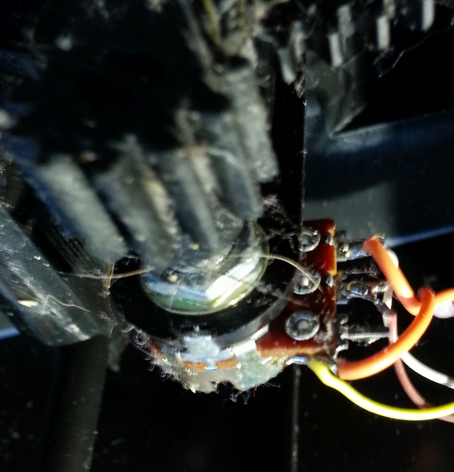
For the receiver of the tripwire, I'm using a small light-dependent resistor (LDR) module. Back when I started with electronics, I created simple screw-terminal breakout boards of various components to aid rapid prototyping - there's 3 terminals, Vcc, LDR output, and ground (via a 10K resistor). To help filter light, I found a red Tic-Tac box, which should filter out most ambient light, but allow the lasers light to shine through.
To threshold the LDR output, I created another low-battery circuit as I've used before in the pedal-keyboard project. This allows for the sensitivity of the receiver to be adjusted, and a digital output to be triggered once the threshold is crossed. I found part of a board which contained the transistors that this circuit would need, and just required some jumping of wires. The resistors were recycled from junk-bin ones which had their legs snapped off.
After applying copious amounts of hot glue to hold it all together in an old business card box, the receiver circuit did work for a brief period, before one of the wires snapped. Hopefully tomorrow I'll only need to re-solder a those wires to finish that circuit, then I can move onto setting up the laser and reflector.
 |
| Rough diagram of how this thing should work... |
Day 2 (Tuesday Evening)
Fixed the snapped wire from yesterday, & tested the receiver circuit. The next stage is to make it do something useful. I found an old wireless doorbell which I can repurpose.
|
|


The receiver can trigger the 'button' part of the bell, which will then notify the 'bell' which I'll convert into a handheld device to notify the user of the detector being activated.
 |
| The transmitter being tested before putting together. |
Days 3 & 4 (Sat and Sun)
Wired in a relay to control the transmitter, and worked on how to power the circuit. As space is limited, I've used a 9V battery, running through a TS7805
regulator to provide 5V to power the detector circuit, and 2 diodes in series to drop the power to approx 3V for the laser pen. The doorbell transmitter runs of 12V, but for convenience I've opted to just power that from it's own battery, as they have quite a long life anyway.
Also rewired the doorbell receiver to a vibration motor from an old Playstation controller, and wired a AA battery holder in place of the original D cell ones. This should result in a pocket-size receiver that vibrates when the laser beam is broken.
 |
| The receiver - battery pack on reverse. |
A fortnight later....
Day 5 (Sat)
Some bad planning on my part meant that the output signal from the laser receiver was the inverse of what was needed - so effectively the doorbell component was triggered whenever the laser wasn't broken. Not very useful.
Created a not-gate with a simple transistor and wired that in place, however the resulting current was not enough to trigger the relay, so I added another transistor to amplify the not-gates output.
In the end, the whole project took about 3 weeks, but only about 6 days where I was actually working on it. It's a complete bodge, and hideously impractical, but was a nice challenge and works surprisingly better than expected.
 |
| The finished product, receiver (left) and laser detector (right) |