After having our son, my partner wanted me to make her a memory box where she could keep all the trinkets and keepsakes from his birth.
As it is something of an old stereotype that such things would be kept in an old shoe box, I wanted to mimic that aesthetic.
The box is made from iroko, sides of approx 1cm, joined with box joints. The base is simple hardboard, rebated into the sides.
I didn’t really want to add hardware such as hinges as I felt it would detract from the shoebox aesthetic, so I opted for a simple lift off lid.
The lid itself is made from a thicker piece of iroko, with trim added around the edges.
In order to provide a good friction fit, a piece of plywood, wrapped in t-shirt fabric, matching the boxes internal width and depth was added to the lid. This holds the lid on without rattling around, and incidentally hides the “bonus feature” of the box.
The bonus feature
Of course I can’t do anything normal like just make a box.
During his first few weeks, whenever our son sneezed, he would follow it up with a little noise that sounded like he was saying “oh..”. Of course it was incredibly cute and a memory we want to cherish forever.
What my partner didn’t know at the time, is I had managed to catch this on video, and I wanted to surprise her with it.
A few years ago (around 2015-2016 I think), Sainsburys brought out a Christmas biscuit selection box which included a gadget for recording a message that would play when the biscuit tin was opened.
Somewhere along the line somebody I know must have got one, I scavenged the gadget from the tin once it was empty, and it spent the past few years sat in my electronics junk drawer, waiting for a project to be used in.
The circuit board is clearly designed as a disposable product – it is powered by 3 button cell batteries, which are riveted to the PCB itself. Whatever microcontroller powers it is hidden under an epoxy blob, and the only other notable features are a small microphone, speaker, a light dependent resistor (which is how it detects if the box is opened), and a small switch used to start and stop recording.
First thing to do was to drill out the rivets and get rid of the dead batteries. Rather than replace them with more button cells, I opted for wiring in a AAA battery holder, I just had to follow the PCB traces and connect it at the right point.
The microphone is pretty much as crap as you would expect for something of that size in a ostensibly disposable product, so I needed a better way to record the audio.
To do that I replaced the microphone with a 3.5mm jack and coupling capacitor. Once I’d copied over the recording, I removed that as well to save space, and also removed the record button to avoid overwriting.
Then it was simply a matter of hiding the electronics in the box. This was done by carving out a hollow in the middle of the lid. The ‘inner lid’ of plywood that was also used to create a friction latch, added sufficient depth to the lid in order to hide the battery and PCB.
The underside of the lid with hollow for PCB/battery and speaker.
The t-shirt fabric that covered the inner lid also hid the circuitry, while also allowing enough light to pass through to activate the recording.
Clap switches are an old automation gimmick from the 1980s. Basically the circuit hears a noise above a given volume (amplitude), and activates.
This project is an attempt to refine that idea, to create a switch that does the same, but responds only to a given sound (frequency).
This was inspired by watching my partner fail miserably playing South Park - The Stick of Truth.
In the game during battles, there is a timed button press during an attack that increases damage. Timing these button presses was not going well...
That noise triggers at the time the button press is required, so I started thinking about how that noise could be listened for, and the button press triggered.
Band-pass filters
This system relies on the use of a band-pass filter. There are plenty of explanations around about these and how they work, so I won't reinvent the wheel here.
For the purposes of this project, the key point is if the input has a frequency between the low and high thresholds, it is allowed through. Frequencies outside of those thresholds (bands) are rejected.
These can be built in hardware as circuits, but also in software on regular computers.
Fast-fourier Transform (FFT)
This is a well-known algorithm that, in simplistic terms, takes input over time (such as audio), and breaks it down into the frequencies it's composed of.
I'll admit, my understanding of FFTs is similar to the relationship most people have with their household appliances - know how to use it, but can't really explain how it works under the hood. There's plenty of detailed explanation for the more mathematically inclined.
So the basic concept is this
Pipe the audio input into the FFT
The FFT converts it into the frequency domain
Zero out all the values for the frequencies that fall outside of the range we're 'listening' for.
Do an inverse FFT transform, which turns the frequency domain data back into time-domain (i.e. back to real audio). This gives us sound where everything except for the range we're listening for is muted.
This can then be passed into a regular 'clap-switch', where we trigger if the volume of the sound is above a given level.
Finding the target frequency
This part of the process can be trickier than it initially seems. Sounds are composed of many frequencies, so it is necessary to select a frequency range that is unique to the target part of the audio.
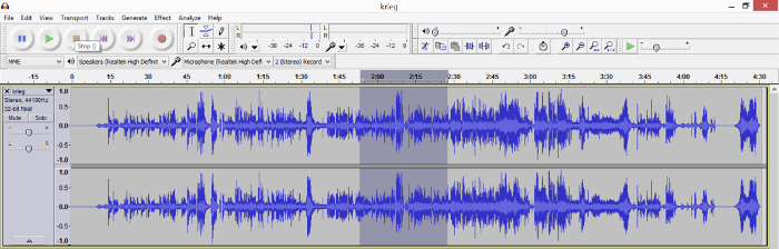
To start with, I extracted the audio from the above video clip using FFMPEG, and opened it up in Audacity. This initially shows the audio waveform.
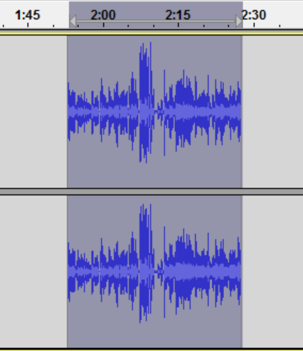
Select the area containing the sound, and select Tools, Plot Spectrum.
This will show the frequencies that exist within the selection. However, this doesn't give us all the answers. Save the plot (I just took the below screen-shot and used that). Then select another parts of the audio and repeat the exercise. Then basically it's a case of spot-the-difference, looking for a frequency spike that appears in our target audio but not the other samples.
A sample spectrum from elsewhere in the audio.
The segment containing the target sound. Circled are frequency spikes not seen in the rest of the audio,
Hardware
To run this switch I'm going to use the Next Thing Co CHIP. This is the same system I used for the TV desk project years ago. Unfortunately these are now discontinued, but there are still many ARM-based SoCs running Linux out there.
Potentially this could be distilled down further on to a smaller microcontroller, although I'd have reservations about how far you could reduce the resources until the processing time introduces enough lag to make it too slow to use.
As well as effectively being a 'proper' computer, the CHIP has general purpose IO pins, like most microcontrollers. This can provide the interface for the output of the 'clap' switch. In this case, for the sake of example I'm just hooking up a simple LED that will blink on detection of the given sound.
Although the CHIP does have microphone pins and the ability to switch it's video pin from the jack to be an audio in, for the sake of prototyping, I found it much easer to just use a cheap USB adapter which has microphone and headphone sockets.
Power comes from a standard USB phone charger.
Control is done via a serial connection to my PC, using Minicom.
Software
As the CHIP is a full-blown Linux distribution, there's lots more flexibility in the software that we use. I ended up using Java and the Apache Commons Math library.
The basic OS was pre-installed, Java 8 JDK was installed from here.
The Java code listens to the microphone input, and allows the user to load a JSON file containing details of the filter to apply - this made testing and refining the filter easier. The values are the start and end of the frequency range to listen for, and the threshold of amplitude to trigger the output (This figure can be a bit of trial and error based on how loud the input is, and can vary if the input volume varies.)
It can also be controlled via command line to either pass-through the audio to the headphones as-is, or post-filter - i.e. you hear what the 'clap' circuit would hear.
Some configuration was required to enable the GPIO pins to be activated on boot. To do this, the necessary commands (below) are wrapped in the bash script
(Refer to the CHIP docs for what exactly these mean)
This is set to run on boot by adding the below line to /etc/rc.local
sh /etc/init.d/preparegpio.sh
Finally, for the Java code to trigger blinking the LED, it triggers another SH script. I went this route as I intend to develop the Java code into a more general purpose audio tool, so didn't want to tie the code too closely to the hardware I'm using for this project.
It also has the benefit that the audio processing doesn't wait for the GPIO operation to complete, thus reducing the lag.
While it certainly does respond to the input audio as expected, there is definitely some processing lag, as can be seen as the video progresses.
This isn't entirely unexpected, and could be overcome by throwing more computing power at the processing (The CHIP is a 1GHz processor), or possibly further optimisation of the code (or porting it to C or similar).
That might be the subject of a follow up project at a later date, but for now, this demonstrates the idea.
I, like a lot of people, work in an organisation that uses access control cards that we need to carry at all times - usually on a lanyard around our neck. I also like to listen to podcasts and music while I work, so that often means having a pair of earphones around my neck too. The combination of the two often results in tangling and general annoyance, so I thought I could combine them.
I revisited the cable tidy that I previously created (it was one of the first 3D printed objects I created, and definitely in need of some improvement).
I've since moved away from OpenSCAD in favour of Blender as my 3D skills have improved - The new design can be found on Thingiverse.
The plan is use a scaled down version of the cable tidy to control the part of the earphone wire from the connector to the split
and then have each earphone attached to the lanyard, coming out at the top with enough slack to reach my ears.
The cable tidy is straightforward enough, there are three pieces - the two halves of the inner section, and the outer ring. They all friction fit - once printed, just lightly sand necessary edges until a snug fit can be achieved.
To create the lanyard I started with two promotional ones I'd received (they tend to be a common hand-out at conferences and trade shows). The main one also has a side-release buckle just up from the dog clip (the clip that holds the card... yes, I had to Google what it was actually called), which would also solve another annoyance - having to remove the lanyard while driving to get through the car park security gate.
The second, sacrificial, lanyard, is slightly narrower. This lanyard was cut into strips which would be stitched to the main lanyard to create a channel to contain the earphone wire.
I stitched up one side, put the earphone wire in place, then stitched down the other side to lock it in place. The length of wire was too long to begin with - this was partially by design - I didn't want to leave the top (earphone side) just open, as I could forsee wear and tear putting too much strain on the stitching. What I did instead was stich it 'too high', then cut down the middle of the sacrificial lanyard to pull the earphone through and create enough slack, and then stitch up behind it, so that there was more, stronger stitching supporting it.
I repeated this exercise for the other earphone, and it was done. One snag was that the earphones had a small button halfway down the wire for the right-hand earphone, which was a little too big. A dab of contact cement held this in place, and unless looking closely, it's not noticeable.
I tested using the lanyard at work before the Christmas break. As with all wearable tech, there's always the concern that it looks too goofy, so I picked a day where the office wasn't too busy, to see what, if any comments were made. All the feedback I heard was positive - for the most part it just looks like I have the headphones resting around my neck, and as for the cable tidy, a lot of others have keys and other items hanging from their lanyards, so it doesn't seem too out of place.
A new update to the Soundboard application on Google Play has been released.
What's New
A new Tone Generation feature, which allows the user to generate sine-wave tones and play them back.
Also a bug fix - on the DTMF screen, swiping between the screens would effectively have the effect if the DTMF buttons being stuck in a pressed state, causing a continuous playing of the tone. The layout of that screen has been amended to reduce the occurrence of this happening.
Usage
From the app's start screen, use the Tone Generator button, or swipe across to access the tone generation module.
On that screen, use the slider or text box to select your chosen frequency, set the duration, and hit generate to play the tone
The module is also subject to the volume controls of the rest of the application - go to preferences in the menu and you'll be able to choose whether or not to dynamically set the volume level on playback, and set the volume level if you so wish.
Support
As with all my apps, it is free, and as such, I am not in a position to offer any kind of official support, so use entirely at your own risk.
If you have any trouble with it, then feel free leave a comment or tweet and I'll try to help as and when I can, but I make no guarantees.
In some ways my workplace is very much like this - anything that could be misconstrued as an innuendo, even remotely, will inevitably have people calling out "hey, phrasing!", "That's what she said..." etc, etc.
Combining that with this "Bullshit button" from The Last Leg:
.. and I had an idea.
To cap it all off, at work we were having a clear out of some cupboards, and I found this:
It plays a dog-barking noise when pressed. I'm told it was used for some kind of team building thing long before I joined the company. Weird.
By this point it must be pretty obvious where this project is headed...
The teardown
First things first, see how much space in the button there is to work with, and what parts can be reused.
The single PCB contains a controller under a blob of epoxy, as was expected, so I'll need to replace that. However, the same PCB contains the actual button, so it'll need to stay in place. To allow that I just cut the traces connecting the button to the PCB, and scraped off some of the solder mask in order to provide connection points for my replacement controller.
The electronics
As this was intended to be a quick and easy project, I had to make do with what I could find in my electronics junk box. I couldn't use the same MP3 trick that I used in the Swear Jar project, as what I had available was too large for the buttons' case.
Whichever controller I used needed to have enough memory to store the audio data, which ruled out a lot of micros, so I ended up recycling an old arduino micro (ATMega328)
To make room for the arduino, the battery compartment had to be removed - I would instead use coin cell batteries. This would still work, but come at the cost of a reduced battery life.
The audio
To capture the original audio, I used the same technique I covered here to create a WAV file. After using Audacity to crop and edit down the relevant clip (Archer saying "Uh, Phrasing"), I used the EncodeAudio application from HiLoTech to turn it into a header file (sounddata.h in the code below)
The software
The code used on the arduino was based around the PCMAudio example, but I needed to modify it to incorporate some power saving - to account for the reduced capacity of the coin cell batteries. Code listed below:
Text-to-speech support added to enable use within the soundboard.
Intro screen provides more detail about usage, front screen button auto loads file list on main soundboard.
Usage
On open the user will be presented with a two buttons, one will take them to the new Text-to-speech interface, where they can enter text and play it back to inject custom phrases into their soundboard.
The second button will load the regular soundboard as in previous versions, but will automatically load the files into the list (no need to select Load from the options menu).
It is also possible to swipe between the screens as well, so pre-recorded audio can be mixed with TTS-generated speech.
Note, if you swipe across to the soundboard screen from the start of the app, you will need to select Load from the options menu to populate the list.
Support
As with all my apps, it is free, and as such, I am not in a position to offer any kind of official support, so use entirely at your own risk.
If you have any trouble with it, then feel free leave a comment or tweet and I'll try to help as and when I can, but I make no guarantees.
My latest Android app is now available on Google Play.
A simple soundboard application. Save some MP3 or OGG files to your phone, load up the app and play them at the touch of a button.
Tap the file names to play
To keep the sound playback levels constant, the app allows you to set a volume level independent of the current volume. On playback, the app sets the volume to that level, plays the sound clip, then returns the volume to it's previous level.
Designed to be used with phones using an adapter such as the one
described in my previous post, the app also works well with Xbox Live headsets (Xbox 360), and in
theory should work with any device you're capable of connecting your
phones audio output to.
The app was built for and tested on an HTC One M9, but should work with any recent flavour of Android.
Usage
Initially, copy the audio files to your devices storage, into a directory called SoundboardFiles.
Open the app, hit the menu button and select load, and you'll get a list of the files as in the first screenshot above.
Go to preferences in the menu and you'll be able to choose whether or not to dynamically set the volume level on playback, and set the volume level if you so wish.
Going back to the main screen, simply tap the filenames to play the file (the app will deal with the volume adjustments automatically.
The volume control menu
If you're struggling to find audio clips to use in the
See this post
for a guide on creating sound clips from YouTube videos and other
online sources.
Support
As with my other apps, it is free, with a simple ad banner at the bottom of the main screen.
As such, there is no official support, although I will respond to any comments via this site or twitter as best I can.
Update
An unintentional (but useful) outcome of this project is that the connector used in this project is the same as the one used on Xbox 360 headsets, so this same device could be used to inject audio, such as a soundboard, into your in-game chat.
Original post below:
I got asked to build another phone audio interface for a colleague who spends a lot of time on the phone and wanted a way to play back pre-recorded audio to save repeating himself.
Unfortunately the existing one I build before is for traditional POTS (plain old telephone system), but the office uses VOIP phones.
I don't have a spare VOIP phone to mess with, so had to look at other options.
The normal headset jack
The phone has a headset port, using a 2.5mm jack socket, and the headsets plug has 3 rings. Given the the headsets themselves consist of just a microphone and earpiece, it stands to reason the pinouts are mic, speaker, and ground.
I don't have the actual pinout for this particular brand of headset, but I have worked with similar ones in the past and typically the tip is the microphone, ring is speaker, and base is ground.
I don't have one of those connectors to hand, but found a stereo headset one from an old hands-free kit. That it has an additional ring connection (for the 2nd audio channel) doesn't matter, it'll effectively join up with ground anyway.
In addition to being able to inject audio into the call, we still need to be able to use the phone normally, so I've used an XBox 360 controllers headphone port to provide a passthrough for the phone headset.
The quick hand-drawn wiring diagram I used. An artist I am not.
Testing this circuit revealed a slight problem, having both the audio source and microphone connected resulted in the microphone becoming inaudibly quiet. In hindsight, this is likely due to the audio source being amplified and the mic not. A simple switch added to the circuit to allow quick switching fixed that.
Adding a simple switch at this point sorted the problem.
The finished adapter in the obligatory tic-tac box
So it's the run up to Christmas, and at work we're having a desk decorating competition. This of course means lights, and an excuse for some colourful, blinky-type projects.
Most supermarkets are selling these battery operated chains of coloured LED lights for a couple of quid. They run off 3 AA batteries (4.5v) and are just static lights.
If you look closely there's actually 3 wires – this is likely because
the different colour LEDs have different voltage drops. When I get to
dismantling them later we'll know which are on which wire, but my guess
is that red and orange are on one line, green and blue on the other.
Turns out I was right.
My idea is very simple, wire an transistor
onto each line so that they can be controlled independently, then
connect a stereo jack to the base, with each channel (left/right)
connecting to alternating transistors, so each audio channel will
control one strand of lights. The principle is similar to the design I
used on the space invaders alarm clock project,
but instead of the alternating current being responsible for changing
the colour, it'll be the audio channel.
The circuit diagram. The only components I need to add were the transistors, the
stereo socket, and a USB cable for power (the resistors were already
part of the assembled lights.)
The finished circuit, with the ever-useful TicTacs box enclosure.
The flickering of the lights works, but the frequency is very rapid, which seems to stop the LEDs reaching full brightness. Potentially this could be alleviated by adding capacitors to smooth out the switching, but as the effect varies quite drastically depending on audio source, it's not really an issue. The next challenge is finding a playlist that uses the lights to best effect!
As the past few projects have been quite frivolous gadgets, this time I'm going to do something practical. It turns out this was actually one of the quicker projects I've done and makes a decent weekend project for anyone looking to make a quick upgrade to their cars audio system.
My car as an auxiliary audio input for connecting MP3 players etc. For this I purchased a bluetooth speaker adapter on Ebay for about a tenner.
It's a great device to connecting my phone for sat-nav, music etc, but there's a small annoyance in the fact that after getting in the car, it requires me to press and hold the power button for about 5 seconds before it'll turn on and connect to my phone. It's a bit of a first-world problem, granted, but it's kinda irritating, so I've been thinking about how to solve it.
Ideally, it should function like a built-in bluetooth adapter does in many new cars - as soon as the car is powered on, the bluetooth is powered on and connects to the phone.
After some experimenting with various approaches - microcontroller delays, 555 timers, I found the most functional circuit was a simple capacitor delay circuit, combined with a transistor NOT gate & optocoupler, so that the optocoupler is active, effectively holding down the adapter's power button, for 5 seconds, then switched off until the circuit loses power.
A rough schematic of the circuit I used
The completed circuit on top of the bluetooth adapter
Inside the bluetooth adapter.
Powering the circuit was simple enough - I already have a car 'cigarette lighter' to USB adapter with 2 USB ports - one powers the bluetooth adapter, and it powers on with the car ignition, so I added a USB plug to the timer circuit and used that.
Finally, I didn't want to leave exposed wires or circuit boards visible in the car - knowing my luck some paranoid idiot would freak and call the bomb squad or something, so I 3D printed a simple box enclosure which houses the adapter and the circuit nicely, the box itself nestling neatly in the centre console of my car.
The finished adapter in it's 3D printed box, ready to put in the car
Recently at work, management instituted a ‘Swear Jar’ system, to try and limit the use of profanity in the office.
Personally, I really have no issue with swearing - words are just words, but many people don’t share that view, so I understand why they did it.
The problem for me is that now, whenever someone swears, there’s a chorus of people shouting “Swear Jar!” at the person who swore. This, to me, is far more annoying than the swearing ever was.
It give me an idea though. What if the phrase “Swear Jar”, was taken more literally - a jar which swears at you when you put money in?
So, yeah, that’s the flimsy premise of this project. Read on for the full write up, or just watch the video of it in action below. (It should really go without saying that the language in the video may be unsuitable for some people..)
The Jar
As a base, I picked up one of those basic coin-counting money boxes often found that those ‘gadget shops’ which tend to open up in shopping centers selling a bunch of battery-operated plastic junk for a few weeks before they inevitably fail.
The coin mechanism is nothing special, essentially a slider which completes connections at different points to detect different coin values. there's not really anything else of value in the circuitry, it's all hidden behind epoxy blobs, so I scrapped everything else.
Audio
To provide the audio, I’m using an old MP3 player that I had in my junk bin - it’s essentially a 512MB memory stick with three control buttons and a headphone jack.
I enlisted a friend's help in trawling through movie clips on YouTube to get audio clips of profane movie quotes (this is where the previous post came from). The end result being a bunch of clips, all 3 seconds in length.
I wired up a small speaker from the junk bin. Fortunately the internal amplifier in the MP3 player was powerful enough to drive the speaker directly - as it's originally designed just for headphones, I thought it might not have sufficient power.
Controller
As this is just a novelty project, and I wanted to get it done and in the office before the swear jar idea was forgotten about, so I didn't really have time to delve too deeply into interfacing with the MP3 players circuitry. I opted to simply use a microcontroller to imitate human interaction. Conveniently, all the functionality I need from the MP3 player is obtained from just one button.
I opted for an ATTiny2313, using the arduino cores for convenience, and a relay to toggle the MP3 players button. Source code is below.
Power
Another complexity with this project is although the MP3 player doubles as a USB disk, powering it via the USB port only allows it to be used as a memory stick, and disables the MP3 playback functionality. Therefore the only other way to power the device is via it's AAA battery slot, so I required 2 power rails - 5v to drive the microcontroller, and 1.5v to power the MP3 player. This was achieved by using a 7805 to arrive at 5v for the micro, then using that 5v fed into an LM317 to provide 1.5 volts for the MP3 player. The main power input is 9v, which was originally intended to come from a battery, but at the last minute swapped for a wall supply (because I couldn't find a battery)
Block Diagram
The below shows how the different components fit together. As this is a frivolous novelty project, I'm not going to put together a full KiCad schematic - the most complex bit was the TS7805 and LM317 circuit, but there's plenty of existing documentation for those online already.
Timing is everything
The problem that quickly became
evident is that the microcontroller has no feedback from the MP3 player,
so cannot tell if a clip is playing, or even if the MP3 player is
switched on. This is why the audio clips needed to all be the same
length. There is also the issue of switching the MP3 player on, which requires a long press of the button. This is addressed in the setup function of the following code.
The MP3 player also has an auto switch-off function that causes it to turn itself off after a short period of time. This means that if no money is put in the swear jar for a while, the next time someone does, nothing happens, and requires the power to be cycled to reboot the whole thing.
The timing requirements are far too precise - even though all the audio clips used were 3 seconds, over time the slightest variances would add up, causing the microcontroller to lose sync with the audio.
So, I'm finally back after quite a long haitus to focus on my day job and studies. This post originated as a request from a friend who wanted to know how to extract snippets of audio from Youtube videos.
With this method the audio can come from any source that is playable in VLC (so, pretty much anything), but for the sake of this example I'm going to use Youtube, as that was the original request.
Step 1 - VideoDownloadHelper
On Firefox there's a plugin called VideoDownloadHelper which makes it easy to save videos from Youtube locally. If you use a different browser there's probably a similar plugin available.
Go to the Youtube page with the video that you want to save. VDH will auto detect the media and the toolbar button will light up.
Select the file - often there's quality options, usually it's best to just select medium. Save the file.
Step 2 - VLC
In VLC, go to File, Convert/Save, select the file, and click Convert.
In the dialog box, select Convert, and under Profile, select the output format that you require, and supply a destination file. Once that’s done, click Start. Wait for the progress bar to complete, and your output file will be done.
Step 3 - Audacity
Final step is to open that audio file in Audacity, play the audio to find the segment you want in the wave form.
Then select the section (just click and drag), then use the trim option (see icon).
The trim icon
Repeat the process until the desired segment of audio is isolated, then go to File, Export As, then export the file to the chosen format.
I work from home, and my job requires I spend a lot of time on the phone, particularly in conference calls.
I could easily go and just buy a new headset or hands free desk phone, but I already have a general purpose headset that I enjoy using, and frankly, I have accumulated a lot of headsets over the years from various phones, consoles, computers etc.
One of the items I had in my junk bin was an old wall-mounted telephone - the kind where the keypad is on the handset.
Taking the phone apart revealed three PCBs - one in the base unit of the phone, and 2 in the phone itself. One is obviously the keypad, and the other appears to be an amplifier - it was on this board that the microphone and speaker was attached.
Making the connections - the main part of the interface, is really very simply. Just cut away the microphone and speaker, and replace them with connectors.
The next step is the hang up button. Hang up buttons are press-to-break - pressing the button breaks the circuit, so as it stands connecting this to the phone line will result in your line being open.
To add extra complexity on the phone I was using the hang up button was a Double Pole Single throw switch (DPST) - this means that the switch effectively controls two circuits.
When closed, the switch connects the 4 contacts (seen de-soldered above) as follows: 1 & 2, 3 & 4
Fortunately I managed to find a 'normal' DPST switch on an old amplifier PCB in my junk bin, so wired that in place.
Also, in order to make the end product neater, I removed the coiled cable between the base and handset, and cut away the keypad - I can always use my existing phone to dial. Besides, the keypad may prove useful in a future project.
All that remained was to create a new case for it. I was able to recycle an old business card box, and 3D printed a basic front panel for the connectors.
The finished box, just connect an audio source to input, and some headphones/speaker to output, and away you go.


.png)
.png)
.png)
.png)
.png)
.png)
.png)


