Monday 27 October 2014

Remastering Tiny Core Linux

Tiny Core Linux is a lightweight Linux distribution designed for Live CD usage. Its low system requirements and small footprint also make it a good candidate for reviving older computers or as a base for building virtual machine appliances.

Unfortunately the remaster tool it includes, which is meant to allow for custom Live CDs to be created with chosen software pre-installed, seems to be buggy, and continually failed when I tried using it, so this is the alternative way I found to remaster TCL.

Step 1
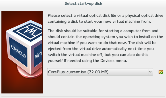
Create a basic virtual machine and boot with the TCL Live CD. I used the CorePlus-current.iso, which has some extra software on there, but is still sub 100MB.


Once it's booted to the desktop select TC Install.


Select USB-HDD, whole disk and 'sda' options on the first screen.

Click through the next two screens (formatting options and boot options)


On the install type I checked the Installer Application option as I might need it in my intended application later, but it's optional.

Click through to the next screen where you're selected options will be repeated back to you, and select Proceed.

When it's done installing, shutdown the VM, remove the Live CD image and restart, so that it boots from the HD.


Step 2
Go to apps, and install the software that you require. In my case I installed Open JDK and Filezilla. (Filezilla also requires libiconv to be installed)


Reboot using the TC Exit options (from the menu go to Logout). The backup options there will essentially create a blank mydata.tgz file structure for you to use later.

Once rebooted, copy the /mnt/sda/tce1 folder off the VM to the host system/memory stick whatever (As I installed filezilla I FTP'd it to another server on my network.)

Step 3 (Optional)
On the host system, edit the mydata.tgz that you copied over, and add in any necessary files that you want on the Live CD. Thanks to the reboot that you did in step 2, mydata.tgz will have a basic file structure in place, that maps to the home and opt directories of the live CD. Also it puts in a couple of SH scripts, bootlocal.sh and shutdown.sh - these handle things that you want to execute on boot and shutdown respectively, edit those if you need to.

Step 4
Use an ISO editor (I used ISO Master).
Open the LiveCD, and navigate to it's 'cde' directory
Copy your mydata.tgz to the ISO, and replace its onboot.lst, and 'optional' directory with your own.

Navigate back to the ISOs /boot/isolinux directory and edit the isolinux.cfg file.
Find the line

TIMEOUT 600

This line causes it to sit on the bootloader screen for 60 seconds, unless the user selects and option.
I want my live CD to boot without user interaction, and that delay is redundant, so I edited it to

TIMEOUT 10

which allows a 1 second delay before continuing to boot the default option.


Save the edited ISO. To test, setup a blank VM like you did in step 1, and select the edited ISO as the boot medium. TCL should load, with your apps and files already there.

Sunday 19 October 2014

HD44780 LCD to Raspberry Pi

My interest in electronics initially started as a result of PC modding back in the late 90s/early 2000s. Back then, most desktop computers were typical beige boxes - it was all about the internal hardware, not the design of the system itself, and it fell to the users to make then any more interesting than that.

A common mod was to install a LCD screen into the front of the desktop to display things such as system stats (CPU, Memory, temperature), notifications (Email/MSN/ICQ!) or the currently playing track on Winamp.

My old desktop PC has long since been retired, but I still have the LCD that I used, and now I've found an excuse to use it again.

Nostalgia aside, I have a project underway that is going to require a headless Raspberry Pi. While it's easy enough to SSH into the Pi and get to a terminal from another computer, it would also be handy to have at-a-glance stats available.

Fortunately, there's a way to connect a HD44780 LCD (standard text one like mine) to the Pi, using the standard GPIO pins, and leaving the serial pins free (which I'll need for another part of the project).

The thing to be wary of when looking for instructions on connecting one of these displays to a Raspberry Pi is that there are many 'LCD backpacks' and specially designed accessories out there. I'm not using any of those, simply the Pi, the LCD, and a potentiometer to adjust contrast on the display.

Adafruits wiring guide is a good start. While it's aimed at 16x2 displays, it does apply to those of other sizes (the one I'm using is 4x20. They keep referencing their 'Pi Cobbler', though this is simply a breakout board they sell, and it's easy enough to map to the standard Pi pins.
 
A couple of points worth reiterating - the GPIO pins are designed for 3.3v operation, but the LCD for 5v. To avoid 5v being sent to the GPIO, connect the RW pin of the LCD to ground. Also worth noting is the difference between LED and EL backlight. EL has a higher current draw, so trying to power it from the Pi might overload it (LED however is fine). The displays can operate just fine without the backlight, so it's optional anyway. Mine is EL, but I don't really need it, so just left it unconnected.

I was relieved to see that LCDproc is still around. This was the software I used back with my old desktop, so I chose to stick with this instead of the Python solution Adafruit suggest. The pins that they recommend using are slightly different, but can be adjusted in the LCDproc config.

  • To install LCDproc on the Pi, run
    • sudo apt-get install lcdproc
  • Open the config file
    • sudo nano /etc/LCDd.conf 
  • find the line
    • Driver=curses
  • and replace with
    • Driver=hd44780 
  • Find (Ctrl+W) the [hd44780] section and change the ConnectionType line to
    • ConnectionType=rpi 
  • Underneath add the pin mappings in the format shown below 
D7=18
D6=23
D5=24
D4=25
EN=8
RS=7 
 
Even though there is a driver file (hd44780.so) in the driver path, it doesn't seem to work.
Some Google searching found someone else with a similar issue and a replacement driver file, see steps 4 through 10 on there. (though note there's some differences in the rest of their setup to mine, so beware.)

Once that's done, restart LCDd with
  • sudo service LCDd restart
and you should see some text on your LCD!

The default LCDProc screen - the ribbon cable at top left connects to the Pi GPIO.
The small PCB in the top right is a 3.3v to 5v level converter that is to be used for a different project.


Sunday 21 September 2014

New App/Update: Bluetooth Macro and Voice Input

This new app is an update to my previous Bluetooth Macro Input app. Unfortunately, for technical reasons, I could not issue this as an update to the existing app.


The new version focuses more on the voice recognition and transcription features of the app,

Now any macros you store in the Macros subfolder can be selected by voice. For example, if you store your macros in
<DEVICE STORAGE>/BluetoothMacroFiles/
and have a macro called
<DEVICE STORAGE>/BluetoothMacroFiles/Macros/Hello world.txt

Then the voice command "Hello World" can be used to load and play back that macro.

Usage
Usage guide for the original file-based macro system can be found here.
Previous update notes are available here.

Requirements Changes
Companion hardware is still required, see the original post for details.

The minimum required version of android is Honeycomb (Android 3.0)

Sunday 24 August 2014

New app / Major Update: Web Media Grabber


This is a replacement for my previous 'RSS Media Grabber' app. This version is no longer restricted to RSS feeds, and can retrieve media from most web sources - RSS, Web page, Twitter feed, etc. It is also no longer limited to certain media types, and can retrieve any file extensions listed by the user.
The previous version will remain available on the Play Store for a while, until users have migrated over (this version couldn't be released as a simple update due to an issue with package signing keys)


Usage
When using the app for the first time, use the menu button and select "Add New Source".
On the next screen, enter the URL for the feed, and give a folder name (this will be where the app stores the files it downloads - eg, if you enter "MyFolder", the directory will be sdcard/MediaGrabber/MyFolder/)
Enter the file types you wish to extract, separated by spaces as per the example, eg "jpg gif mp3" etc.
Select OK to return to the main screen, and select menu->Load sources. This will list all the sources you've added.
Select one of the sources to be prompted to retrieve the feed. Select OK and it will load the feed, grabbing any media with your chosen file extensions, and saving them to the folder.

You'll then be able to view the downloaded media through your app of choice.

Monday 11 August 2014

Analog pedal to USB keyboard


A lot of my electronics junk box consists of old videogame peripherals, which are often tricky to re-purpose because of proprietary connectors, peripherals, etc.

These pedals, for example, connect to a Playstation steering wheel by a fairly normal 9-pin serial connector, but the wiring isn't standard. Even if it were, most modern PCs no longer have serial ports, so a serial to USB adapter would be needed, and a software solution to make the input useful.

What I'm really after is a drop-in system, that can provide input as if it were a regular keyboard or mouse. The easy way out would be to use a microcontroller to emulate one of those devices, but I want to avoid throwing one at every problem, so I'm going to opt for only using discrete components and a scavenged keyboard PCB.

I'm going to re-purpose this keyboard PCB from the phone scanner project that I did a while ago.

The pedals themselves are essentially just a couple of potentiometers, so in it's simplest form, the contacts for a key could be wired to the pedal. This would mean that as the pedal is pressed, it will reach a point where the resistance is low enough for the signal to pass, however this is quite a simplistic option.


It also seems a shame not to make some use of the fine control of the analog input, so what I have in mind is a two-stage trigger type system - so that a light press of the pedal completes one key, and a complete press sends a second key. For example, a light press could be 'Ctrl', and the full press 'X', to create a pedal for the standard Cut shortcut.

So what's needed is to find a way to create a threshold for when to close the keyboard circuit and trigger the buttons. In order to so this, we can use a low battery circuit, such as the one shown here.

Rather than wait for the power to drop though, we will be using the pedals' potentiometer in place of R4 in the diagram. As the voltage will remain the same, using the pedal to change the low voltage level will change the sensitivity of the circuit, so that when pressed, the LED is triggered. We will also replace the LED in that circuit with an optocoupler, connected to the keyboard matrix for the key that we want.

To create the second stage of the trigger, another copy of the circuit is created, but using a higher value resistor in place of R3, and sharing the same R4 (the pedal). This one will trigger when the pedal is pressed further.
The circuit, with a test potentiometer in place (the upside-down PCB just contains some screw terminals for attaching the potentiometer - see right) Each pair of leads on the left go to the respective terminals on the keyboard PCB (below)
The screw terminal on the underside (on a separate PCB as I scavenged it from the junk box)

The keyboard PCB. The old IDE cable is there to make it easier to patch together the key matrices - In the picture above the leads from the pedal circuit board are connected.


Finally, power is added to the pedals from the keyboards USB connector - see left. This is sufficient to power both the keyboard and the pedal circuit


I have currently only done this for the right-hand pedal, but the same process could just as easily be done for the left (perhaps for other modifier keys - one shift, one ctrl etc).


A test of the pedal in various applications showed it to work, and has proved its usefulness for tedious key combinations in games (such as toggle run/slide etc)


Wednesday 30 July 2014

App Update: Bluetooth Macro Input

The Bluetooth Macro Input app has been updated and is now available on Google Play.

New Features

As well as it's existing ability to send text files stored on phone, it is now possible to use voice recognition to transcribe voice to text and send that text via bluetooth in the same way, effectively allowing your phone to act as a dictation machine for your computer, without needing to install additional software on your computer.

Please note the voice recognition uses Google's voice recognition API. As a result, I do not have any control of the quality or accuracy of the voice recognition. It does also mean that Internet access is required to use the voice recognition feature.

Usage guide for the original file-based macro system can be found here.

Requirements Changes

Companion hardware is still required, see the original post for details.

The minimum required version of android is now Honeycomb (Android 3.0)


Sunday 13 July 2014

Dog-controlled treat dispenser part 2


This is the second part of my project to create a dog treat dispenser that my dog, Jack, can operate on his own. For the first part, click here.

Building an enclosure
I thought about 3d-printing an enclosure for the control box, but before I commit the time and effort to designing and printing one, I want to make sure that the project works - and that Jack actually uses it.
So for now, I've managed to fit the electronics into an old business card box, with basic cut outs for the buttons and wiring. It's not pretty, but it works.

The enclosure (the croc clips are for power - final version recycled a charger from a Playstation portable)

The floor switch is connected to the control box by a length of old VGA cable - it's nice and sturdy, and has more than enough wires for this project.

The components for the floor switch


In use
I finally managed to get a short video clip of Jack using it


Future improvements 

The floor switch is too light, as you can see in the video, when Jack uses it, he knocks it across the floor, so I've since mounted it to a bit of wood which helps hold it in place.

The small metal tin that I used to make the contact area larger & easier for Jack to use, ended up making the capacitive switch too sensitive - it basically became like a motion sensor - so I removed that, and used the original metal disc (about 15mm diameter) instead. Although the disc itself is smaller, it still manages to detect capacitance from contact anywhere on the switch, so it works just fine.
The floor switch - unfortunately the hot glue made a bit of a mess, but it's all contained on the underside of the switch, and actually helps diffuse the light a bit.


Source Code (Arduino cores for ATTiny2313
int latchPin = 8;
int clockPin = 12;
int dataPin = 11;
int capBtn = 7;

int plusBtn = 3;
int minBtn = 4;

int enabledLight = 5;

int motorPin = 6;

int treatCount = 0;
int valToDisplay = 0;
int timerBypassPin = 9;
long myTime;
boolean treatEnabled = false;

void setup() {
  //set pins to output so you can control the shift register
  pinMode(latchPin, OUTPUT);
  pinMode(clockPin, OUTPUT);
  pinMode(dataPin, OUTPUT);
  pinMode(capBtn, INPUT);
  pinMode(enabledLight, OUTPUT);
  pinMode(motorPin, OUTPUT);
  pinMode(plusBtn, INPUT);
  pinMode(minBtn, INPUT);
  pinMode(timerBypassPin, INPUT);
  digitalWrite(motorPin, LOW);
  digitalWrite(enabledLight, LOW);
  treatCount = 3;
}

void loop() {
  if (digitalRead(plusBtn) == HIGH) {
    treatCount++;
    if (treatCount > 8) { treatCount = 8; }
    delay(500);
  }
  
  if (digitalRead(minBtn) == HIGH) {
    treatCount--;
    if (treatCount < 0) { treatCount = 0; }
      delay(500);
  }
  
  if (digitalRead(timerBypassPin) == HIGH) {
    treatEnabled = true;
  }
  
  if (
      ((millis() - myTime) < 0) ||
      ((millis()-myTime) >= 3600000)
     ) {
    myTime = millis();
    treatEnabled = true;
  }
  digitalWrite(enabledLight, treatEnabled);

  if (digitalRead(capBtn) == HIGH) {
    if (treatEnabled) {
        digitalWrite(enabledLight, LOW);
        treatEnabled = false;
        treatCount--;
        digitalWrite(motorPin, HIGH);
        delay(3000);
        digitalWrite(motorPin, LOW);
    }
  }
  

  switch (treatCount) {
    case 0: valToDisplay = 0; break;
    case 1: valToDisplay = 1; break;
    case 2: valToDisplay = 3; break;
    case 3: valToDisplay = 7; break;
    case 4: valToDisplay = 15; break;
    case 5: valToDisplay = 31; break;
    case 6: valToDisplay = 63; break;
    case 7: valToDisplay = 127; break;
    case 8: valToDisplay = 255; break;
  }


  digitalWrite(latchPin, LOW);
  shiftOut(dataPin, clockPin, MSBFIRST, valToDisplay);
  digitalWrite(latchPin, HIGH);
  
}

Tuesday 24 June 2014

Dog-controlled treat dispenser

I picked up one of these treat dispensers from Maplins on a whim - one of those "I'm-sure-I'll-find-a-use-for-this-someday" things. Subsequently I started wondering if I could train my dog, Jack, to use it (with some modifications, obviously)

An initial attempt involved simply wiring a switch to a footpedal for Jack to step on. That lasted all of 10 seconds as the plastic lid I'd repurposed as a pedal cracked under his weight.

One of the things that attracted me to the gadget in the first place was the capacitive button that it used. A quick test with my phone screen showed that dog's paws can operate capacitive switches.

Simply extending the leads alone wouldn't be enough. Although I want to give Jack the freedom to get his own treats, I still want to keep control over how many!

The touch sensors board has simple connections - just power, and leads out to the motor. I didn't really want to waste time modifying the board, as it's all small surface-mount components. Since I know the motor was only driven one direction by the board, I simply connected an optocoupler to the motor outputs. A couple of pull-up resistors later and the switch was done.

The finished capacitive button PCB with optocoupler


I connected a metal lid in place of the small capacitive disc to make it more dog-friendly.

Now onto the human's control system..

My original plan was to use something web connected such as an old android device, so that I could give Jack treats whilst out at work, but in practice, it was totally overkill, so I opted for a microcontroller based system instead.

The only controls I really need are to limit the number of available treats, set a time limit so he doesn't eat them all at once, and a way to see how many were available.

I found an old PCB with two buttons on it in my junk box. One button to add a treat, one to remove.
 
The salvaged button PCB (I believe it once belonged to a toaster...)


For a display I went with a 10-segment LED, controlled by a shift register. Due to the limitations of the shift register, the maximum treats available at any one time is 8 - which is more than enough anyway. The remaining 2 LEDs are left unused.
The 10 segment display (3 treats available) - the bottom 2 LEDs are not used.


The time limit I chose to fix at 1 hour in the microcontroller. As it's impossible to precisely measure the amount of treats that will be dispensed, the motor was set to a 3 second interval.

Finally I added a small LED module to the pedal, that lights when the timer ticks down and a treat is available, so that Jack could see when he can get a treat. According to the Pavlovian theory, he should soon learn that light=treat.

The LED module (it's just from one of those battery operated 'cupboard lights' you see in nearly every pound shop) - for this project I just connected a jumper over the button.


As with other projects I opted for using an Attiny (in this case the 2313) with the Attiny arduino cores, as they make it nice and easy to prototype with Arduino and switch to a regular AVR for the end product.

Stay tuned for part 2 - building an enclosure for it, some pictures of the completed project, source code, and hopefully some pictures/video of Jack using it.

UPDATE - Part 2 is now available here.

Tuesday 10 June 2014

Android App: RSS Media Grabber

My second android app is now available on the Google Play store. It's a port of a desktop Java application I wrote a while back, which will retrieve image media from RSS feeds - useful for web comics/cartoons, pic-of-the-day sites etc.


Usage
When using the app for the first time, use the menu button and select "Add New Source".
On the next screen, enter the URL for the feed, and give a folder name (this will be where the app stores the files it downloads - eg, if you enter "MyFolder", the directory will be sdcard/RSSMediaGrabber/MyFolder/)
Select OK to return to the main screen, and select menu->Load sources. This will list all the RSS feeds you've added.
Select one of the feeds to be prompted to retrieve the feed. Select OK and it will load the feed, grabbing any image media, and saving them to the folder.

You'll then be able to view the downloaded media through your photo app of choice.


Future development plans
  • Wider media selection (MP3 for podcasts etc).
  • Integrated media viewer/player
  • Scheduling to check feeds at set intervals.

Support/Feedback
As with my other apps, it's free (ad-supported), and I welcome feedback. Unfortunately I'm not in a position to offer any kind of official support for this, so use entirely at your own risk. If you have any trouble with it, then feel free to contact me on twitter/G+/leave a comment, and I'll try to help as and when I can, but I make no guarantees!

Any feedback, particularly with regard to different phone/tablet hardware and android versions is appreciated.

Thursday 22 May 2014

Android App: Bluetooth Macro Input

UPDATE - Please note this version of the Bluetooth Macro Input app is no longer supported. Although it's still on the Play store, it will not be updated in future. Please consider migrating to the new Bluetooth Macro and Voice Input app instead.
 
A while ago I posted this snippet of Arduino code for an upcoming project. Unfortunately with a looming redundancy and several courses on the go at the moment I've not had the free time to follow up until now.

All the code does is read a character from the serial pins of the arduino, then outputs that character as a keyboard keystroke using the keyboard emulation functionality of the Arduino Leonardo variants.

The rest of the hardware is very simple - just a bluetooth serial module, such as one of these - connected to those pins. There's just 4 pins - power, ground, TX and RX.

With that done, and the arduino sketch uploaded, the rest of the work is in the android application, which is now available for download by clicking the button below.


What it does
You can provide a library of snippets of text on your devices external storage (any ASCII filetype is fine), and then this app can access them, and send them via bluetooth to the arduino hardware, which emulates a USB keyboard and types the contents out.
This is handy for maintaining a library of code/command snippets that you might want to use across different computers or devices. (Or if, say, your day job requires you to often type the same thing on a computer that you have little control over software/config wise...)

Requirements
  • The hardware described above.. Without it, the app is kinda pointless.
  • Supports versions of android from 2.2 (Froyo) upward, though only tested on a Samsung Galaxy S3.
  • Bluetooth serial device (115200 bps)
  • Permissions
    • Requires bluetooth and external storage access.

Usage

To run the app, first turn on bluetooth.
When you first run the app, you'll need to enter the MAC address of your bluetooth device - you should be able to find this in the docs of your serial device (or printed on it). Once done it should automatically connect.
Create or move your text snippet files to the a folder on the SD card under BluetoothMacroInput directory.
Use the Menu key in the app to bring up the menu, which is basically just the folder structure of the directory - click on your chosen file and it'll load it into the text view. Click 'Type' to have the device start typing your text.
Depending on your external hardware, you might need to adjust the delay value (if the typed text is garbled, then you need to increase the number)


Future Development plans
  • One-button input for frequently used commands.
  • Mouse emulation using phone touchscreen/sensors
  • Dynamic macro recording (using USB host passthrough for a keyboard)
  • General UI improvements..

Support/Feedback
Unfortunately I'm not in a position to offer any kind of official support for this, so use entirely at your own risk. If you have any trouble with it, then feel free to contact me on twitter/G+/leave a comment, and I'll try to help as and when I can, but I make no guarantees!

Any feedback, particularly with compatibility on different hardware (both android devices and Bluetooth/keyboard hardware) will be much appreciated.

Monday 14 April 2014

Space Invaders alarm clock mod

I'm very conscious of the fact that the last two posts have been quite text-heavy, so here's a lighter weekend project.

I was once given a Space Invaders alarm clock. It's shaped like one of the aliens from the game, the 'pixels' of the LCD display are shaped the same, and when the alarm goes off it makes the aliens sound and moves from side to side as they did in the game.


Which is all well and good unless you have a small bedside table, and the clock just rolls off the edge every morning...

The lazy answer would be to just build a barricade, or some kind of stand that would stop the wheels turning.

Opening up the clock reveals a small PCB, with wires neatly labeled, and a small motor which operates a worm gear to move the wheels.


My plan is to replace the motor, and use it's wires to power some LEDs which I will place in the 'eyes' of the model.

Although labelled "M+" and "M-", the motor wires polarity changes - to allow the change of direction. This is great for motors, but reversing the polarity on an LED will likely result in the magic smoke escaping.

To get around this - and also provide a neat colour change effect - each eye will have 2 LEDs in parallel, and arranged in opposite directions. The LEDs of each colour for each eye will be in series (see below). Also don't forget a 100 Ohm resistor at one of the ends (doesn't match with one)

One green and one red LED per eye. As the current changes the LEDs will alternate


This means that when the current is flowing one way, it can't get through one LED, so moves through the other. When it changes direction, it can no longer get through that one, so it diverts to the other, effectively 'blinking' each LED in turn.

Then it's just a case of drilling eye holes, poking the LEDs through, and reassembling (I also used hot glue to act as a diffuser for the eyes)

Each stage of the end result. It doesn't roll off the table anymore, but I didn't count on it looking a lot more sinister.


Thursday 3 April 2014

Creating a VirtualBox test system for Raspberry Pi development


Firstly, I'm going to walk through the process of setting up a Ubuntu Virtual Machine (VM) on VirtualBox, which I will use as a test environment for developing for the Pi.

Download the Ubuntu ISO from here if need be.
With VirtualBox installed on your PC. Go to New, and walk through the wizard, allocating memory, and creating a virtual hard disk.

Once that's done, boot the machine, and you'll get a "first-run" type prompt, asking you to select an installation source - direct it to the ISO you downloaded earlier.

Once the VM boots, select Install to hard disk, and walk through the graphical wizard for that. Once complete, reboot the virtual machine.

Once rebooted, login, and open a terminal.
Follow the same instructions to update the system and install the LAMP stack as we did in the post about setting up the Pi.

Once that's done, the next step is to install the VirtualBox 'Guest Additions'. These allow easier interaction between your host system and the VM.
Select this from Devices -> Install guest additions at the top of the VM window. After a few seconds you'll be prompted to run the software in the VM (you'll also be asked to authorise the installation)

Let that run through, and then reboot the VM. Now would be a good time to take a snapshot (Machine->Take snapshot). This effectively creates a backup of the system state at the time it was taken, so if you test something and screw it up, it's fairly trivial to get the system back to how it was.

Now, create a shared folder between the host and the VM - this'll make it easier to move files between them. Right-click on the folder icon at the bottom right of the VM window, and select shared folders. Click the 'Add' button at the right hand side of the dialog that appears - fill in the path, name, and options for the share (Uncheck read-only, check auto mount and make permenant)

You'll now find you have a folder on the virtual machine under /media/sf_FOLDERNAME, where FOLDERNAME is the name you gave your shared folder (eg, mine was named Temp, so on the VM it's /media/sf_Temp). You'll also find you can't access it.
To fix this, in the terminal enter

sudo gpasswd -a USERNAME vboxsf


replacing USERNAME with your own username. You will need to reboot for the changes to take effect.

The final step is to allow the host to access the VM's server.
Go to Machine->Settings->Network, and click Port Forwarding on the network adapter you're using (1 by default)
Click Add, then enter the name (HTTP), host port (I chose 8080), and guest port (80). Click OK.
Now when browsing to localhost:8080 on your host machine, you should see the "It works" page of the web server on the VM.

Take another snapshot here.

This was meant to be a short intro to the main development, but seeing as it's already a lengthy post, I'm going to leave it here, and pick up the rest of the development later.

Monday 31 March 2014

Raspberry Pi LAMP Server

This is a simple guide to setting up a Raspberry Pi computer as a 'LAMP' (Linux, Apache MySQL, PHP) server.

I'll be using it at a later date to create a simple PHP-based To-Do list type system, which I'll cover in later posts.

Download and install the latest version of Raspbian from the Raspberry Pi website.
As I'm using linux, the command I needed was:

sudo dd bs=4M if=2014-01-07-wheezy-raspbian.img of=/dev/sdh

Boot up the Pi and go through initial setup:
  • Expand filesystem
  • Change user password
  • Boot to console
  • Enable SSH Server
  • Force audio through 3.5mm
  • Update tool to latest version
Finish the setup tool and from the command line run updates:

  • sudo apt-get update
  • sudo apt-get upgrade
Install the LAMP stack:

  • sudo apt-get install apache2 php5 mysql-client mysql-server
During this installation process you'll be asked to provide a root password for the MySQL server.
(Optional) Install PHPMyAdmin


  • sudo apt-get install phpmyadmin

This should boot the PHPMyAdmin installer tool:
  • In the first screen select the web server to configure (apache2).
  • Select yes to configure database for phpmyadmin with dbconfig-common.
  • Enter the root MySQL password. Create a phpmyadmin password for the sql server.
Now would be a good time to save the progress made. Shutdown the Pi with
  • sudo shutdown -h now
Once the systems shutdown, remove the memory card and make a backup of the cards data. I use the dd command again to create a gzipped image


  • dd if=/dev/sdh | gzip > /path/to/backups/backupname.img.gz

This allows backups to be restored just as easily, using the command

  • gunzip -c /path/to/backups/backupname.img.gz | dd of=/dev/sdh
If you want to run the Pi 'headless' - without screen or keyboard, now would be a good time to disconnect them.

Once the backup is done, put the SD card back in the Pi, and reboot.
Give it a little while to reboot, and then from your P, connect to it via SSH. On linux this is a command like

  • ssh HostnameOrIP -l pi
Once logged in, you can control the Pi from the command line as you were able to previously.


Monday 24 March 2014

Motion activated Pac-Man lamp


Version 2

Migrated the control over to an ATtiny25, using the ATtiny cores for Arduino.
I found a ported version of the IRRemote library on Github. It looks as though this port was for a specific purpose, and lacked the IR codes I needed, however it was easy enough to port the necessary parts from the orignal IRRemote library.

This is the revised code:

#include "IRremoteTiny.h"

IRsend irsend;

#define PIR PB2 // pin 7 on ATtiny

void setup(void) 
{
  DDRB &= ~(_BV(PIR)); // Set as input
  DDRB |= _BV(PB3);

}

void loop(void) {
  
  if (digitalRead(PIR) == HIGH) {
    digitalWrite(PB3, HIGH);
    for (int i = 0; i < 3; i++) {
      irsend.sendNEC(0xF7C03F, 32);
      delay(40);
    }
    delay(10000);
    for (int i = 0; i < 3; i++) {
      irsend.sendNEC(0xF740BF, 32);
      delay(40);
    }
  } else {
    digitalWrite(PB3, LOW);
  }
}


Version 1
I was given a Pac-Man lamp for Christmas.
It's a simple RGB colour changing lamp that is remote controlled.


In my flat the hallway can be quite dark, and when leaving, there can be a few seconds between turning the flat's hall light off, and the external hall light being triggered.

I was considering getting a simple plug-in 'night light' type thing, but I didn't want something that stayed on all the time. And besides, I wanted to put Pac-Man to good use.

As it was a Christmas gift, it didn't seem right pulling it apart straight away, so the plan is to create a motion-triggered device that mimics the remote.

The first thing is to find the remote protocol being used.
To do this use a IR receiver module (I scavenged one from a VCR that was on the junk pile), and hook it up to an Arduino, using Ken Shirriff's arduino IR library. Using the 'IRrecvDump' sample sketch you can find the details of the protocol in the serial monitor - it'll look something like

F7C03F
Decoded NEC: F7C03F (32 bits) Raw (68): 15538 8950 -4200 700 -400 700 -400 650 -450 700 -400 700 -400 650 -450 650 -450 650 -450 650 -1500 700 -1500 700 -1500 650 -1550 650 -450 650 -1500 700 -1500 700 -1500 700 -1500 700 -1500 650 -450 650 -450 650 -400 700 -400 700 -400 700 -400 700 -400 700 -400 650 -1550 650 -1500 700 -1500 700 -1500 700 -1500 700 -1500 650 F740BF

Decoded NEC: F740BF (32 bits) Raw (68): 26860 8950 -4200 700 -400 700 -400 650 -400 700 -400 700 -400 700 -400 700 -400 650 -450 650 -1550 650 -1500 700 -1500 650 -1550 650 -450 650 -1500 650 -1550 700 -1500 650 -400 700 -1500 700 -400 700 -400 650 -450 650 -400 700 -400 700 -400 700 -1500 650 -450 650 -1550 650 -1500 700 -1500 650 -1550 650 -1500 700 -1500 650

My first thought that the pacman remote looks very similar to the remotes that tend to get bundled with rolls of RGB leds, and I had a couple of those going spare, so perhaps one of them could've been sacrificed, however performing the same test with those showed that they use a different protocol, and so wouldn't work.

The second thought was to make use of an old Sky TV remote - they have a feature that allows the protocol to be programmed to control several makes of TV, but after a while trying various codes, it appeared that the one I was after wasn't one of them.

So the final option was to use the arduino itself for sending the signal. It seemed a bit overkill, but I can always migrate it to a smaller microcontroller when I have one spare. The IR led was taken from the old Sky remote.

The next stage is to wire in the PIR sensor (motion detector)

I used one of these:


They're a simple 3 pin setup - Vcc, Ground, and Data. Data simply goes high for a few seconds when motion is detected.
It can be easily wired in, just effectively like a simple button.


Here's the code I used - when motion is detected, turn the lamp on for 10 seconds, then off again.

#include <IRremote.h>

IRsend irsend;

void setup()
{
  pinMode(4,INPUT);
  pinMode(13, OUTPUT);
}

void loop() {
  if (digitalRead(4) == HIGH) {
    digitalWrite(13, HIGH);
    for (int i = 0; i < 3; i++) {
      irsend.sendNEC(0xF7C03F, 32);
      delay(40);
    }
    delay(10000);
    for (int i = 0; i < 3; i++) {
      irsend.sendNEC(0xF740BF, 32);
      delay(40);
    }
  } else {
    digitalWrite(13, LOW);
  }
}

Wednesday 19 March 2014

Telephone audio interface

I work from home, and my job requires I spend a lot of time on the phone, particularly in conference calls.


I could easily go and just buy a new headset or hands free desk phone, but I already have a general purpose headset that I enjoy using, and frankly, I have accumulated a lot of headsets over the years from various phones, consoles, computers etc.

One of the items I had in my junk bin was an old wall-mounted telephone - the kind where the keypad is on the handset.

Taking the phone apart revealed three PCBs - one in the base unit of the phone, and 2 in the phone itself. One is obviously the keypad, and the other appears to be an amplifier - it was on this board that the microphone and speaker was attached.

Making the connections - the main part of the interface, is really very simply. Just cut away the microphone and speaker, and replace them with connectors.

The next step is the hang up button. Hang up buttons are press-to-break - pressing the button breaks the circuit, so as it stands connecting this to the phone line will result in your line being open.

To add extra complexity on the phone I was using the hang up button was a Double Pole Single throw switch (DPST) - this means that the switch effectively controls two circuits.
When closed, the switch connects the 4 contacts (seen de-soldered above) as follows: 1 & 2, 3 & 4

Fortunately I managed to find a 'normal' DPST switch on an old amplifier PCB in my junk bin, so wired that in place.

Also, in order to make the end product neater, I removed the coiled cable between the base and handset, and cut away the keypad - I can always use my existing phone to dial. Besides, the keypad may prove useful in a future project.

All that remained was to create a new case for it. I was able to recycle an old business card box, and 3D printed a basic front panel for the connectors.

The finished box, just connect an audio source to input, and some headphones/speaker to output, and away you go.

Monday 10 March 2014

3D printed cable tidy

Update 28/12/2017
I've revised the design of the cable tidy, and it's now up on Thingiverse.
The post covering the new design and why I created it can be found here.

For the purposes of testing the 3D printer, I'd just grabbed some files from Thingiverse.

This, however, is my first attempt at 3D printing something of my own design.

The next big choice is to select design software. As I come from more of a programmer background than design, I settled on OpenSCAD.This allows you to design objects with script, rather than manipulate the objects directly.

Once designed, the file is rendered, and can then be exported to STL format, which can in turn be used by Slic3r (can be done from within RepetierHost) to convert the STL to Gcode, which is then passed to the printer.

The inner piece - the cable will pass through the middle channel,
The outer piece - a bolt will run through the central hole to mount the inner piece.

The idea is the cable runs through the gap on the edge of the outer piece, through the middle channel of the inner piece, and out the other side of the out piece. So when the inner piece is rotated, the cable is wound around it.

Once printed, I attached a piece of clear plastic to the top to complete the enclosure (I could've 3D printed that, but as it's a flat plastic disc, it seemed wasteful to do so).

Mounting that was more of a pain that I'd thought. Hot glue alone had too much flexibility, so I added in a few miscellaneous screws to provide additional support (This was also worsened by trying to tidy a fairly thick USB charger cable - this tidy is best left to thin cables, such as headphones)

Some Sugru around the edges of the plastic finished the job:
The finished job - twist the blue edges to retract the cable


A few more lessons learned:
  • Remember RepetierHost has a pause button - handy if you need to switch rolls of filament mid-print.
  • Avoid needing to change rolls mid print in the first-place!
  • Make sure the bed is heated before starting to print, it's more important than you think.
  • Give thought to the integration of non 3D printed parts, make sure mounting holes are there if necessary.


Sunday 9 March 2014

K8200 3D Printer review

Years ago, back when 3D printing was pretty much limited to the RepRap, I had this grand idea of building a 3D printer.

Problem was, I was fairly new to electronics, and DIY in general, so my skillset was, well, non existent.

Despite the failure of that project, I was still keen on the technology, and have been keeping a close eye on the commercial offerings. The downside to those options being both the price, and buying an 'off-the-shelf' printer seemed like the lazy way out to me.

Thankfully, Maplin has started selling the Velleman K8200 printer as a kit. This keeps the price to a more modest level, and being self-assembly, reduced my laziness guilt of not building one from scratch.


In the post-Christmas sales, I noticed the kits were on offer, so I finally caved and bought one.


I was planning to do a series of build posts about it here, but the truth is there's nothing much to report that isn't already covered in detail - the manual is a comprehensive 619 pages!

First attempted print - a Mobius Strip from Thingiverse


A couple of pointers I will offer though:

  • The leads on the thermistor for the hot end are very fragile. The guide does warn about it, but it's worth reiterating...
  • You'll have some bits left over. At least I did. Not sure if you're meant to, but mine works OK.
  • It won't work perfectly first time. Expect to have to tinker with it from time to time. Also, be prepared to lose a fair bit of filament in failed prints to start with. 
  • When putting the X carriage inside the frame (page 96 on my version of the manual), there's a picture that shows the carriage fully in the frame. The picture appears too early - the subsequent pages mention about sliding additional nuts into the frame, and actually means slide the first supporting rod of the x carriage into the frame, add the nuts, then the second supporting rod.

Thursday 6 March 2014

Quick Update

This is some code for an Arduino Leonardo that will receive character data from the serial pins, then echo the character through USB as keyboard input to the PC.
This will form the basis of a bigger project that'll be the subject of another post, but for now, here's the code:


void setup() {
  Serial1.begin(115200);
  Keyboard.begin();
}

void loop() {
  if (Serial1.available() > 0) {
    byte inChar = Serial1.read();
    Keyboard.write(inChar);
    Serial1.write(inChar);
    delay(10);
  }
}

Tuesday 18 February 2014

Phone-based document scanner


Recently  I moved home, and in the process of packing up my belongings, I realised how much of my stuff is just paper - Old notebooks, documents, paperwork, etc.

I didn't particularly want to take it all with me and I had neither the time or the inclination to sort through it all by hand, so I started looking at ways to digitise it.

A flatbed scanner would've taken far too long, and I didn't want to go buying new hardware.

My phone (Samsung Galaxy S3) has a pretty good camera. The resolution is high enough to be able to read text from a page, and it's ability to take multiple pictures in succession meant speed wasn't an issue.

Using it by hand however can be a problem. Results were too inconsistent - shakiness caused blurring, inconsistent distance meant time was lost waiting to refocus.

So I built this simple jig from some wood scraps to hold the phone at the optimal distance.


It's an improvement, but the vibration from tapping the screen to take the picture was still causing some distortion.

After some messing around with various options - IOIO board, custom camera apps, etc. I realised that when I was using a USB-OTG adapter with an external keyboard, the stock camera app would treat the enter key as a shutter button.


Rather than waste a whole keyboard on this, I remembered I had a PCB from one in my junk box that was destined for a project that never materialised.


It already had the key matrix wired to a connector from an old IDE cable, so all it took was some probing with a breadboard jumper wire to find the connections for the Enter key, and wiring in a button.

A bit of Sugru later to make the button more comfortable, and I had a quick way of digitising my old documents.

Next Steps
  • An update to the stock camera app stopped it recognising the keyboard as the shutter button. I've been using the new voice commands instead, but it's a lot slower. Maybe switch camera apps / make a new one.
  • Software to analyse all the scans I've taken to help organise.