Sunday, 24 August 2014
New app / Major Update: Web Media Grabber
This is a replacement for my previous 'RSS Media Grabber' app. This version is no longer restricted to RSS feeds, and can retrieve media from most web sources - RSS, Web page, Twitter feed, etc. It is also no longer limited to certain media types, and can retrieve any file extensions listed by the user.
The previous version will remain available on the Play Store for a while, until users have migrated over (this version couldn't be released as a simple update due to an issue with package signing keys)
Usage
When using the app for the first time, use the menu button and select "Add New Source".
On the next screen, enter the URL for the feed, and give a folder name (this will be where the app stores the files it downloads - eg, if you enter "MyFolder", the directory will be sdcard/MediaGrabber/MyFolder/)
Enter the file types you wish to extract, separated by spaces as per the example, eg "jpg gif mp3" etc.
Select OK to return to the main screen, and select menu->Load sources. This will list all the sources you've added.
Select one of the sources to be prompted to retrieve the feed. Select OK and it will load the feed, grabbing any media with your chosen file extensions, and saving them to the folder.
You'll then be able to view the downloaded media through your app of choice.
Monday, 11 August 2014
Analog pedal to USB keyboard
A lot of my electronics junk box consists of old videogame peripherals, which are often tricky to re-purpose because of proprietary connectors, peripherals, etc.
These pedals, for example, connect to a Playstation steering wheel by a fairly normal 9-pin serial connector, but the wiring isn't standard. Even if it were, most modern PCs no longer have serial ports, so a serial to USB adapter would be needed, and a software solution to make the input useful.
What I'm really after is a drop-in system, that can provide input as if it were a regular keyboard or mouse. The easy way out would be to use a microcontroller to emulate one of those devices, but I want to avoid throwing one at every problem, so I'm going to opt for only using discrete components and a scavenged keyboard PCB.
 |
| I'm going to re-purpose this keyboard PCB from the phone scanner project that I did a while ago. |
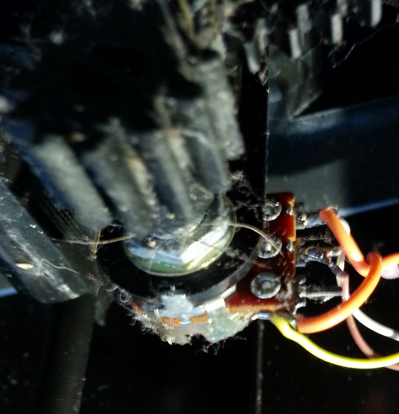
 The pedals themselves are essentially just a couple of potentiometers, so in it's simplest form, the contacts for a key could be wired to the pedal. This would mean that as the pedal is pressed, it will reach a point where the resistance is low enough for the signal to pass, however this is quite a simplistic option.
It also seems a shame not to make some use of the fine control of the analog input, so what I have in mind is a two-stage trigger type system - so that a light press of the pedal completes one key, and a complete press sends a second key. For example, a light press could be 'Ctrl', and the full press 'X', to create a pedal for the standard Cut shortcut.
So what's needed is to find a way to create a threshold for when to close the keyboard circuit and trigger the buttons. In order to so this, we can use a low battery circuit, such as the one shown here.
Rather than wait for the power to drop though, we will be using the pedals' potentiometer in place of R4 in the diagram. As the voltage will remain the same, using the pedal to change the low voltage level will change the sensitivity of the circuit, so that when pressed, the LED is triggered. We will also replace the LED in that circuit with an optocoupler, connected to the keyboard matrix for the key that we want.
To create the second stage of the trigger, another copy of the circuit is created, but using a higher value resistor in place of R3, and sharing the same R4 (the pedal). This one will trigger when the pedal is pressed further.
 |
| The keyboard PCB. The old IDE cable is there to make it easier to patch together the key matrices - In the picture above the leads from the pedal circuit board are connected. |
Finally, power is added to the pedals from the keyboards USB connector - see left. This is sufficient to power both the keyboard and the pedal circuit
I have currently only done this for the right-hand pedal, but the same process could just as easily be done for the left (perhaps for other modifier keys - one shift, one ctrl etc).
A test of the pedal in various applications showed it to work, and has proved its usefulness for tedious key combinations in games (such as toggle run/slide etc)
Subscribe to:
Posts (Atom)


