As I mentioned in my previous post when I was restoring the sewing machine, the electronics were in a pretty bad state.
I believe the pedal was meant to allow for variable speed input, but in reality it acted just like a simple on/off switch, and pressing the pedal down the whole way tripped the circuit breaker.
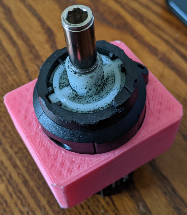
 |
| Inside the motor housing once the rotor had been removed. |
So I decided to just try and replace all of the electronics with modern equipment, but retained the original casings to try and maintain the rustic aesthetic. I figured with modern advances in electronics it is quite likely that a lower power, modern motor would be able to provide comparable performance to the old one (the analogy that springs to mind is the state of modern cordless power tools versus old mains powered ones).
It is clear that the original motor does not have any kind of gearing to boost power – the circuit seemed to be about as basic and simple as it gets.
As I was researching the old motors I did see some mention about potential asbestos hazards – this is near the bushings of the motor – it is intended to support the bushing and act like a self-centering bearing. As I am entirely replacing the motor I had no need for it. With appropriate protective equipment in place I was able to remove it and dispose of it appropriately.
There was also mention about the being asbestos washers in the foot pedal, however my one does not appear to have these – but nonetheless I will not be using this pedal anyway.
One side the case of the me to opened up I was able to pull out the coil windings and rotor, leaving an empty shell. I removed the original connectors.
The screwdriver
To replace the motor I am going to use a cheap cordless screwdriver. Being cordless it should be adaptable to run on a lower power, but given the task that it is designed for, it should still be able to provide enough torque to run the machine due to it’s gearing set up.

In these cordless screwdrivers all the electronics tends to be in the handle, so it is easy to separate out the motor and gearing system from the rest of the device.
With that done I needed to trim off some of the casing to get it to a suitable size to fit in the sewing machine motor case.
The only modification I needed to make to the sewing machines motor case was to drill out the opening slightly as the shaft of the screwdriver was a little bit wider, however this is not actually visible from the exterior.
To mount the screwdriver, I 3D printed a mount (Github/Thingiverse).
It's simply a friction-fit wedge that goes around the screwdriver body and into the sewing machines original metal case.

To do this I created this (Github/Thingiverse). It fits within a small section of aluminium tube (to prevent wear on the plastic), and over the shaft of the screwdriver. It's locked in place with an allen key (cut flush) that fits as if it were a screwdriver bit and locks into this plastic widget. Finally I locked it all together with some adhesive and wrapped a bit of grip-tape around the aluminium.
Driving and control
To drive a motor I am using a BTS7960 motor driver, controlled by an Arduino (for now, for the purposes of prototyping).
Simply this will be an analog input, which the arduino will translate into pulse width modulation (PWM) and send to the motor driver. This is possibly overkill, but the priority at the moment is too get the machine working – optimization & improvements can come later.
For now, I have a simple potentiometer to set the PWM, and the pedal is actually just a switch cable tied to the legs of the sewing machine. I am hoping to be able to get a treadle foot pedal like those that would have traditionally been part of the table legs that I’m using, and use that – if I’m ever able to find one.
Pulley Belt
The belt connecting the motor to the machine was worn through and hanging on by a thread, so it needed replacing.
There seems to be a lot of various DIY how-to ways suggested to create pulley belts to size, so I started working through those. The results were:
- Pulley belt from an old printer cut to size and stitched together using fishing wire - failed - snapped.
- As above, but joined with glue and stitched - snapped.
- Electrical wire (speaker cable) threaded together, and heat-shrunk to provide a rubberised grip. This seemed promising - it didn't snap at least, but the heat shrink, although intended to provide grip, seemed to have the opposite effect.
After all that, as a temporary measure, I joined 3 nylon cable ties together, just so I could move on to the rest of the project. And as the saying goes "There's nothing more permanent than a temporary fix", it's still going strong.

The motor housing also contained a small lamp fitting. This was previously a mains powered, incandescent, bayonet fitting bulb. However I rewired and replaced this with a 12v LED bulb – much in the same way the I did with the Sunset Sarsaparilla lamp project.
Power
Power was provided by an old desktop computer power supply. This provides 12v lines for driving the motor and the light, and 5v for the logic. Again, this is another quick prototyping move, and will eventually be replaced by something nicer.
Finally all that was left was to oil the machine as indicated in the original manual, and give it a try.