So it's the run up to Christmas, and at work we're having a desk decorating competition. This of course means lights, and an excuse for some colourful, blinky-type projects.
Most supermarkets are selling these battery operated chains of coloured LED lights for a couple of quid. They run off 3 AA batteries (4.5v) and are just static lights.
If you look closely there's actually 3 wires – this is likely because
the different colour LEDs have different voltage drops. When I get to
dismantling them later we'll know which are on which wire, but my guess
is that red and orange are on one line, green and blue on the other.
Turns out I was right.
My idea is very simple, wire an transistor
onto each line so that they can be controlled independently, then
connect a stereo jack to the base, with each channel (left/right)
connecting to alternating transistors, so each audio channel will
control one strand of lights. The principle is similar to the design I
used on the space invaders alarm clock project,
but instead of the alternating current being responsible for changing
the colour, it'll be the audio channel.
The circuit diagram. The only components I need to add were the transistors, the
stereo socket, and a USB cable for power (the resistors were already
part of the assembled lights.)
The finished circuit, with the ever-useful TicTacs box enclosure.
The flickering of the lights works, but the frequency is very rapid, which seems to stop the LEDs reaching full brightness. Potentially this could be alleviated by adding capacitors to smooth out the switching, but as the effect varies quite drastically depending on audio source, it's not really an issue. The next challenge is finding a playlist that uses the lights to best effect!
So far we've got an e-Cigarette and an air pump wired together to produce a cloud of smoke. Now what we need is to find a way to control it and install it covertly in my car.
I don't want the trap to spring too early, I need to give them time to get comfortable in the car and get started, for it to be believable.
Also, the motor driver chip will need some logic control, so it makes sense to use a microcontroller to provide the logic and the timings.
As I mentioned in the previous post, left to it's own devices, the eCig's coil gets rather hot, so in order to counter that I wanted the microcontroller to only switch it on in 5 second bursts, then wait 5 seconds for it to cool down.
I used an ATTiny26, for no technical reason other than I have a lot of them spare.
The Videos
I was hoping to use this to prank as many people as possible, and get some good video footage, but unfortunately only 2 of the videos were really usable. The first, is Craigs "We're all gonna die lads!" reaction, and the second, is Bethany's obliviousness to the cloud of smoke forming around her. Enjoy.
A prank that's been doing the rounds in my office is that if you leave your car keys unattended on your desk, you can expect that your car probably won't be where you left it when you leave for the evening.
I've been kicking around ideas on how to improve on this gag, and at the same time defend my car from it happening to me.
My idea was to orchestrate a scenario of deliberately leaving my key for someone to try and move my car, and setting up a surprise for them when they get in. If I could make the car appear to be breaking down, would they own up thinking they broke the car, or just put the key back and deny all
knowledge?
So, what do we need to make it seem a car's breaking down? Noise and smoke.
The noise is quite simple, take a vibration motor from an Xbox/Playstation controller, wire it up and put it in a small container of screws & random bits of metal, so when it vibrates, we get a metallic rattle.
The smoke, not so easy. All the consumer smoke machines I could find required mains power, and
would be far too bulky to conceal in the car, so I have to roll my own.
Thankfully vaping and e-cigarettes have made battery powered, small, smoke producing devices quite cheap and readily available.
I
purchased a few e-cigarette "Atomisers" from amazon and did some
testing. See this post for a write up of how I wired up the eCigarette.
Unless there's a person 'drawing' on the device, the smoke
cloud just sits there, so I'm going to need to create a pump or fan to
force air through the atomiser.
A quick test with some old computer fans that I had lying around showed that they weren't powerful enough, so I found a battery operated air-mattress pump that would do the trick.
The pump appears quite bulky, but it runs on 4 D Cell batteries. As we're not going to need those, a large proportion can be cut away, streamlining the whole thing.
To drive the motor of the pump, I'm going to use the same SN754410 that I'm using to power the e-Cigarette (this is why I used the SN754410 in the previous post, as it's capable of driving two motors, or in this case, one motor and one e-Cigarette.)
This is how the original circuit was planned. The input voltage is 12v
as this is the most readily available source in the car. (The EN pins
and motor logic will all be connected to the microcontroller - left off
in this diagram).
Testing this circuit turned out that 1 amp per 'motor' wasn't powerful enough to drive the pump, so I ended up putting the eCigarette coil and the pump motor in series, and joined the two motor channels of the SN754410 in parallel to double the available current. This isn't an ideal solution, as the resulting heat of the eCig coil is a bit excessive, but I only need it to work in short bursts, and I can control that from the micro.
The revised circuit
Here is the first working test of the smoke machine:
As the pump makes enough noise, I decided that the vibration motor was a
bit unnecessary, so left that off the final design. Essentially the
device is a simple micro-controlled smoke-machine.
I'm currently working on a project that requires the use of an e-cigarette.
I'm not a smoker, so as far as that aspect is concerned, I might be a little off on the terminology, but eCigarettes, vapourisers, whatever you want to call them, essentially follow the same principle. There's a battery, a small reservoir of vaping fluid, a wick, and a wire coil.
Current is passed through a coil which causes it to heat up, in turn heating a wick soaked in fluid which turns it into a vapour.
We can ignore the battery component, it's only really the wire coil I need for the project. I do however need to control it, so I needed to find a way to interface it.
The coil connects to the battery by a screw-type connector which appears to be specifically for these devices. In addition, the connector also contains a small gap which acts as an air inlet for the user to take a drag on it.
This causes problems when trying to create a connection, as connectors run the risk of blocking the inlet.
Coincidentally I found that a male TV aerial connector is an ideal size to create a push-fit connector. The next task is to decide how to control the current flow. Simply switching it on and leaving it will cause it to overheat.
Coils like this can be controlled in similar way to motors. In fact, the IC I'm going to use to control this is really designed for driving motors, but works fine for the purpose of this.
The chip is the SN754410 H-Bridge motor driver - which is completely overkill for this, but as this is forming a part of a larger project, the reasoning will become clearer later.
The pinout for the chip is available on the third page of this datasheet. Treat the vapouriser as if it was a motor - polarity/direction of travel doesn't matter.
For the motor drivers voltage I'm using 12v, which, again, is overkill for this part in particular, but the coils are very tolerant of it, and use the speed control function of the chip to control how hot the coil gets.
That's all for now, stay tuned for the 2nd part of this project...
One of my friends is a writer, and one of the common complaints I hear is that of “Writers block” - experiencing a creative slowdown and not being able to think of ideas to write.
I experience a similar thing with the projects I'm working on from time to time. A solution I've always sworn by is to just jump in and start doing something – even if it's crappy to begin with, it can always be edited later, and the process of actually taking action helps stir the creativity.
The discussion itself was enough for me to start thinking creatively for ways to overcome writers block. Think a cattle prod, combined with the movie Speed, and you get the idea.
As usual the full write up is below, or here's the video of it in action. Unfortunately there's not much to see, the shock wasn't strong enough to create much of a visible effect - it made my thumb twitch a bit, but seemed very dependent on where the electrodes were placed.
The hardware
As we're administering electric shocks to people with this project, in the interests of safety I didn't feel too comfortable DIY-ing the actual shock circuitry, so I picked up one of these reaction-test toys – the idea of the game each player holds one of the controllers, the light in the centre blinks red, as soon as it hits green, the last player to press their button gets a shock. Simple.
The shock game that's going to form a base for this project
The game in action
The bottom of the unit just contained the main switch, battery compartment and small speaker. None of these are needed in this project, so all found their way into the junk bin.
The top of the PCB just contains the main button (centre, surrounded by
LEDs), a number of players button in the corner, and a few capacitors.
The 4 LEDs around the edge were removed.
There was also a switch on the side which determined the severity of the
shock - either a single one or multiple. I forgot to check which one
was selected when I removed it, so that'll be a surprise when it's done. (This was connected to the green wires in the PCB picture below - effectively I've left the switch open)
I also cut away all the controller wires except for player one - that will be the one we're using.
The controller and it's circuitry
Interfacing & Software
How we're going to interface this is by wiring shut the player one button (so effectively it's always held down), and adding an optocoupler in place of the main game button. Then when receiving the signal to deliver a shock, a new game will be triggered, and player one will be shocked for pressing the button too early.
It looks like a steampunk torture device, but it works.
The wires on the controller side were re-wired to a couple of cheap pound-store bracelets, separated by a few 3d-printed plastic spacers and held together with copious amounts of hot glue.
The typical next step here would be to wire in a microcontroller, usb-serial converter and have the PC direct output that way, but I've done that dozens of times and felt like doing something different, so I'm going to use bluetooth and a Wiimote.
The Wiimote connects via bluetooth and contains several sensors. In truth, it's overpowered for this project, but it does give plenty of room for expansion in the future. We're going to use the vibration motors connections to link up to the shocker.
The dismantled Wiimote we're going to use
The connection itself is very straight-forward - a simple optocoupler between the shock toys' main 'play' button connections and the vibration motor output on the Wiimote.
Power is obtained with a 5V wall-wart supply, brought down to 3.3V for the Wiimote using an LM317.
The finished box and bracelet
The software
The source code for the application can be found on Github. Uses Bluecove and MoteJ libraries.
Update
The initial bracelet didn't work to well in testing, as the angle made it difficult to ensure both sides of the connection were in contact with the arm, so I put together an alternative using an old sweat band with a couple of pennies glued into it.
As the past few projects have been quite frivolous gadgets, this time I'm going to do something practical. It turns out this was actually one of the quicker projects I've done and makes a decent weekend project for anyone looking to make a quick upgrade to their cars audio system.
My car as an auxiliary audio input for connecting MP3 players etc. For this I purchased a bluetooth speaker adapter on Ebay for about a tenner.
It's a great device to connecting my phone for sat-nav, music etc, but there's a small annoyance in the fact that after getting in the car, it requires me to press and hold the power button for about 5 seconds before it'll turn on and connect to my phone. It's a bit of a first-world problem, granted, but it's kinda irritating, so I've been thinking about how to solve it.
Ideally, it should function like a built-in bluetooth adapter does in many new cars - as soon as the car is powered on, the bluetooth is powered on and connects to the phone.
After some experimenting with various approaches - microcontroller delays, 555 timers, I found the most functional circuit was a simple capacitor delay circuit, combined with a transistor NOT gate & optocoupler, so that the optocoupler is active, effectively holding down the adapter's power button, for 5 seconds, then switched off until the circuit loses power.
A rough schematic of the circuit I used
The completed circuit on top of the bluetooth adapter
Inside the bluetooth adapter.
Powering the circuit was simple enough - I already have a car 'cigarette lighter' to USB adapter with 2 USB ports - one powers the bluetooth adapter, and it powers on with the car ignition, so I added a USB plug to the timer circuit and used that.
Finally, I didn't want to leave exposed wires or circuit boards visible in the car - knowing my luck some paranoid idiot would freak and call the bomb squad or something, so I 3D printed a simple box enclosure which houses the adapter and the circuit nicely, the box itself nestling neatly in the centre console of my car.
The finished adapter in it's 3D printed box, ready to put in the car
One of the upsides to creating projects for other people, such as the swear jar, is that it often leads to conversation about other ideas, and becomes a great source of other projects.
A lunchtime conversation with a colleague yielded the idea of a laser tripwire, which could be used around the office to trigger practical jokes, use as a 'boss switch' etc.
The idea of laser tripwires is a bit of an old spy-movie cliche, and for practical use a passive IR sensor would be both easier and more useful, but there's a certain novelty aspect to using a laser that I couldn't resist.
In addition, I've set a couple of additional challenges for myself:
I'm making this a 'speed-run' build, because I'm getting frustrated at the amount of time it's taking for me to complete projects at the moment.
Only use items I already have lying around. My junk bin is full of half-assembled boards and off-cuts of other projects, and I'd like to get rid of them, so what better way than to actually make use of them.
Apologies for this post being text-heavy. The full writeup is below, or if you're impatient, here's a short demo of the tripwire working.
Day 1 (Monday Evening)
I found an old laser pen as the base, the metal case of it makes it difficult to get into, but I managed to hook in a couple of wires to the battery compartment (it runs on 3v). As I couldn't reach the power button to wire across it, I opted for a low-tech tape solution to just hold the button down. Unfortunately this wasn't strong enough, so I wedged the laser pointer in a copper pipe t-junction that was in the junk bin.
For the receiver of the tripwire, I'm using a small light-dependent resistor (LDR) module. Back when I started with electronics, I created simple screw-terminal breakout boards of various components to aid rapid prototyping - there's 3 terminals, Vcc, LDR output, and ground (via a 10K resistor). To help filter light, I found a red Tic-Tac box, which should filter out most ambient light, but allow the lasers light to shine through.
To threshold the LDR output, I created another low-battery circuit as I've used before in the pedal-keyboard project. This allows for the sensitivity of the receiver to be adjusted, and a digital output to be triggered once the threshold is crossed. I found part of a board which contained the transistors that this circuit would need, and just required some jumping of wires. The resistors were recycled from junk-bin ones which had their legs snapped off.
After applying copious amounts of hot glue to hold it all together in an old business card box, the receiver circuit did work for a brief period, before one of the wires snapped. Hopefully tomorrow I'll only need to re-solder a those wires to finish that circuit, then I can move onto setting up the laser and reflector.
Rough diagram of how this thing should work...
Day 2 (Tuesday Evening)
Fixed the snapped wire from yesterday, & tested the receiver circuit. The next stage is to make it do something useful. I found an old wireless doorbell which I can repurpose.
The transmitter PCB
Transmitter button & receiver PCB
The receiver can trigger the 'button' part of the bell, which will then notify the 'bell' which I'll convert into a handheld device to notify the user of the detector being activated.
The transmitter being tested before putting together.
Days 3 & 4 (Sat and Sun)
Wired in a relay to control the transmitter, and worked on how to power the circuit. As space is limited, I've used a 9V battery, running through a TS7805
regulator to provide 5V to power the detector circuit, and 2 diodes in series to drop the power to approx 3V for the laser pen. The doorbell transmitter runs of 12V, but for convenience I've opted to just power that from it's own battery, as they have quite a long life anyway.
Also rewired the doorbell receiver to a vibration motor from an old Playstation controller, and wired a AA battery holder in place of the original D cell ones. This should result in a pocket-size receiver that vibrates when the laser beam is broken.
The receiver - battery pack on reverse.
A fortnight later....
Day 5 (Sat)
Some bad planning on my part meant that the output signal from the laser receiver was the inverse of what was needed - so effectively the doorbell component was triggered whenever the laser wasn't broken. Not very useful.
Created a not-gate with a simple transistor and wired that in place, however the resulting current was not enough to trigger the relay, so I added another transistor to amplify the not-gates output.
In the end, the whole project took about 3 weeks, but only about 6 days where I was actually working on it. It's a complete bodge, and hideously impractical, but was a nice challenge and works surprisingly better than expected.
The finished product, receiver (left) and laser detector (right)
Recently at work, management instituted a ‘Swear Jar’ system, to try and limit the use of profanity in the office.
Personally, I really have no issue with swearing - words are just words, but many people don’t share that view, so I understand why they did it.
The problem for me is that now, whenever someone swears, there’s a chorus of people shouting “Swear Jar!” at the person who swore. This, to me, is far more annoying than the swearing ever was.
It give me an idea though. What if the phrase “Swear Jar”, was taken more literally - a jar which swears at you when you put money in?
So, yeah, that’s the flimsy premise of this project. Read on for the full write up, or just watch the video of it in action below. (It should really go without saying that the language in the video may be unsuitable for some people..)
The Jar
As a base, I picked up one of those basic coin-counting money boxes often found that those ‘gadget shops’ which tend to open up in shopping centers selling a bunch of battery-operated plastic junk for a few weeks before they inevitably fail.
The coin mechanism is nothing special, essentially a slider which completes connections at different points to detect different coin values. there's not really anything else of value in the circuitry, it's all hidden behind epoxy blobs, so I scrapped everything else.
Audio
To provide the audio, I’m using an old MP3 player that I had in my junk bin - it’s essentially a 512MB memory stick with three control buttons and a headphone jack.
I enlisted a friend's help in trawling through movie clips on YouTube to get audio clips of profane movie quotes (this is where the previous post came from). The end result being a bunch of clips, all 3 seconds in length.
I wired up a small speaker from the junk bin. Fortunately the internal amplifier in the MP3 player was powerful enough to drive the speaker directly - as it's originally designed just for headphones, I thought it might not have sufficient power.
Controller
As this is just a novelty project, and I wanted to get it done and in the office before the swear jar idea was forgotten about, so I didn't really have time to delve too deeply into interfacing with the MP3 players circuitry. I opted to simply use a microcontroller to imitate human interaction. Conveniently, all the functionality I need from the MP3 player is obtained from just one button.
I opted for an ATTiny2313, using the arduino cores for convenience, and a relay to toggle the MP3 players button. Source code is below.
Power
Another complexity with this project is although the MP3 player doubles as a USB disk, powering it via the USB port only allows it to be used as a memory stick, and disables the MP3 playback functionality. Therefore the only other way to power the device is via it's AAA battery slot, so I required 2 power rails - 5v to drive the microcontroller, and 1.5v to power the MP3 player. This was achieved by using a 7805 to arrive at 5v for the micro, then using that 5v fed into an LM317 to provide 1.5 volts for the MP3 player. The main power input is 9v, which was originally intended to come from a battery, but at the last minute swapped for a wall supply (because I couldn't find a battery)
Block Diagram
The below shows how the different components fit together. As this is a frivolous novelty project, I'm not going to put together a full KiCad schematic - the most complex bit was the TS7805 and LM317 circuit, but there's plenty of existing documentation for those online already.
Timing is everything
The problem that quickly became
evident is that the microcontroller has no feedback from the MP3 player,
so cannot tell if a clip is playing, or even if the MP3 player is
switched on. This is why the audio clips needed to all be the same
length. There is also the issue of switching the MP3 player on, which requires a long press of the button. This is addressed in the setup function of the following code.
The MP3 player also has an auto switch-off function that causes it to turn itself off after a short period of time. This means that if no money is put in the swear jar for a while, the next time someone does, nothing happens, and requires the power to be cycled to reboot the whole thing.
The timing requirements are far too precise - even though all the audio clips used were 3 seconds, over time the slightest variances would add up, causing the microcontroller to lose sync with the audio.
So, I'm finally back after quite a long haitus to focus on my day job and studies. This post originated as a request from a friend who wanted to know how to extract snippets of audio from Youtube videos.
With this method the audio can come from any source that is playable in VLC (so, pretty much anything), but for the sake of this example I'm going to use Youtube, as that was the original request.
Step 1 - VideoDownloadHelper
On Firefox there's a plugin called VideoDownloadHelper which makes it easy to save videos from Youtube locally. If you use a different browser there's probably a similar plugin available.
Go to the Youtube page with the video that you want to save. VDH will auto detect the media and the toolbar button will light up.
Select the file - often there's quality options, usually it's best to just select medium. Save the file.
Step 2 - VLC
In VLC, go to File, Convert/Save, select the file, and click Convert.
In the dialog box, select Convert, and under Profile, select the output format that you require, and supply a destination file. Once that’s done, click Start. Wait for the progress bar to complete, and your output file will be done.
Step 3 - Audacity
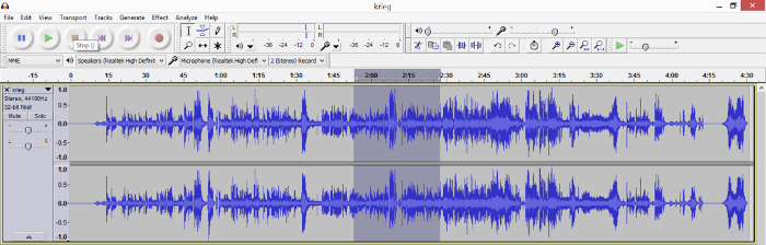
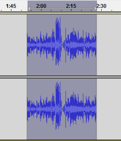
Final step is to open that audio file in Audacity, play the audio to find the segment you want in the wave form.
Then select the section (just click and drag), then use the trim option (see icon).
The trim icon
Repeat the process until the desired segment of audio is isolated, then go to File, Export As, then export the file to the chosen format.


 If you look closely there's actually 3 wires – this is likely because
the different colour LEDs have different voltage drops. When I get to
dismantling them later we'll know which are on which wire, but my guess
is that red and orange are on one line, green and blue on the other.
Turns out I was right.
If you look closely there's actually 3 wires – this is likely because
the different colour LEDs have different voltage drops. When I get to
dismantling them later we'll know which are on which wire, but my guess
is that red and orange are on one line, green and blue on the other.
Turns out I was right.


.png)
.png)
.png)
.png)
.png)
.png)
.png)