Tuesday, 9 August 2022

Multi-tiered triangular planter

I'm pretty sure at some point I said I was done with making planters, but, here we are, here's another.

It's a multi-tiered, 4-segment planter made from pallet wood and arris rails from a dismantled fence.

I've always liked the idea of mixing differing heights in gardens, like with the firepit project, and as we're aiming for a zero(ish) waste approach to the garden, planters are a great means of re-homing soil that is displaced from other projects.

The triangular arris rail is an example of letting the available materials influence the design of the project. In my original sketches I'd planned for a square design, but finding the arris rail led me to using triangles, which actually fits better as the planter is intended to go in a corner.

Likewise, the pallet wood influenced the sizing, as the sizes of the triangle are 120cm, which is a standard footprint for a pallet.

Saturday, 18 June 2022

Fallout New Vegas inspired "Sunset Sarsaparilla" lamp

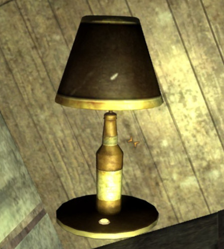
In Fallout New Vegas there is a fictional drink - Sunset Sarsaparilla - and in various locations throughout the game there are these bottle lamps, which served as the inspiration for this project.


I'm not trying to make a perfect replica, but instead just follow the general format of the design.


Lamp

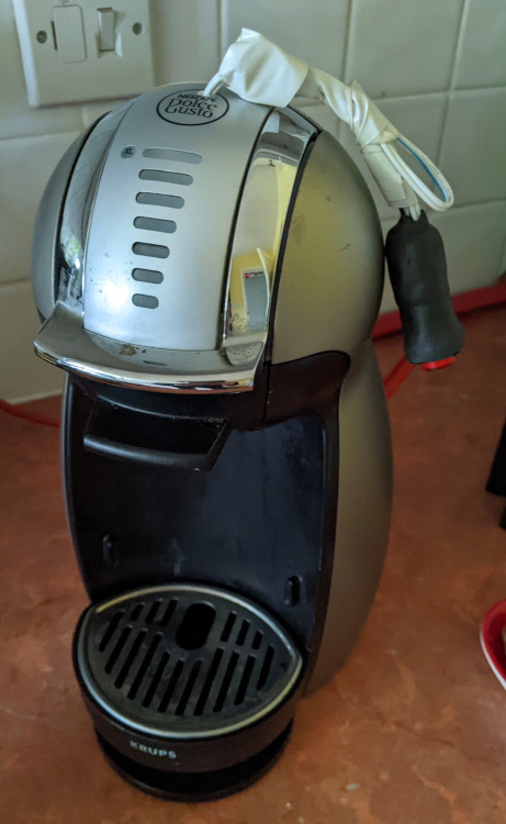
The base lamp I am re-purposing is a basic  bedside lamp. It has a simple stem that lends itself well to this kind of project


Bottle

I found a beer bottle which had no embossing or branding on it other than an easily removed label.

To drill the hole in the bottom of the bottle I created a single-use jig to hold the bottle upside down. I filled the curved base of the bottle with water to act as coolant and lubricant, as excess heat can be a big problem when drilling glass. An abrasive drill bit, normally meant for drilling tile, was used, which worked very well.

In it's simplest guise, the project would just be "Drill hole in bottom of bottle, thread lamp through bottle, done."
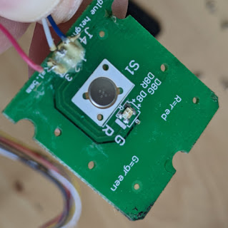
 

Switch

Although I didn't want to make this project an on-the-nose gaming build, I do have some Sunset Sarsaparilla branded bottle caps, which I wanted to use as the switch. However I don't want the sharp-ish edges of the cap exposed, so I encased it in two-part epoxy resin.

This sat atop a simple toggle push-switch poking through from the bottom of the base.


Assembly

Starting with the stem of the lamp, I drilled a small hole in its side, to thread the fairy lights through.

Then the connector end of the fairy lights are threaded through that hole, and the lights themselves wound fairly tightly around the stem

A second, plain brass, bottle cap was drilled to fit the stem of the lamp, and threaded onto the lead for the main bulb.

This was then attached to the top of the stem, and the lead threaded through.

This assembly was then put into the bottle. Before pushing the bottle cap down entirely, by pinching the end of the fairy lights and then rotating the stem, the lights could be unwound, so that they expanded into the bottle.

At this point the fairy lights were tested (with just battery power) to ensure no wires were broken or damaged during assembly.


Power

The original lamp runs on regular mains voltage.


However I'd like to reduce it so that I can add some fairy lights in the bottle for some additional lighting.

There exist 12v DC bulbs for the type of fitting this lamp has (E14 SES), which would typically be used in caravans etc. Obviously it's not just a case of switching the bulb over, else the 12v DC bulb will just get destroyed.

So firstly, I'm removing the plug from the lamp, so it's not connected back to direct mains by accident.

I intend to simply use a 12V wall-wart, which the new bulb can be powered directly from.

The fairy lights that I'm using are powered by 2 CR2032 coin cell batteries (6v), so I'll still need to reduce the voltage to power them.

To do this I'm using a LM317 regulator, with 4.7k and 1.5k ohm resistors to create a 5.4v output voltage

I'm also including a small current-limiting diode on the output to the fairy lights for added protection.
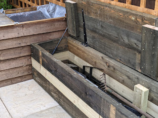
Base

The base of the original lamp, aside from a weight, was hollow. I took the base and flattened it into a simple metal disc.  

My router was broken, so had to be
creative with a forstner drill
I took a piece of chestnut wood, and cut a new base from that, hollowing out the enough to recess the original base disc, and house the additional electronics.

 In the top another hole was drilled from the button

The button that the bottle cap will sit on


End Result


Friday, 20 May 2022

Laser-line Oche for Dartboard

When I built the dartboard cabinet last year, I put a piece of tape on the floor to act as an oche (throw line).

As they say, there's nothing more permanent than a temporary solution, and a year later, the tape was still there, so now it's time to do something about it.

Years ago, back when I first started posting my projects on social media, one of my first Instagram posts was about a (now long abandoned) project to create a 3D scanner:


In this process, a regular laser diode - like one from a laser pointer - is aimed through a transparent cylindrical object. This acts like a prism, refracting the light, creating a line.

The same principle I used back then, is what I'm using this time around. Although this time I'm using a piece of acrylic rod rather than being cheap and trying to use a stem from a broken wine glass...

The Diode

The laser diode that I'm using comes from an old Nintendo Wii lightgun accessory, and was the one I started using in the laser scanner project.


With all the plastic shroud removed, this is what is we're left with


 The Casing

I initially went down the rabbit hole of making a 3D printed case, but in a moment of inspiration, realised that a short section of copper pipe would be perfect.

The pipe is about 1.5 inches long, and we're using two end caps.

One simply has a small hole drilled for the wires to come out of the back


A plastic washer was used to create a mount for the laser diode in the pipe.

The second pipe end cap is used to create the lens assembly.


The lens assembly

A hole was drilled into the end cap, bevelled at the outside for a nicer finish. The hole should be no wider than the diameter of the acrylic rod.

A small piece of transparent acrylic rod was cut, and sanded to make a friction fit in the end cap perpendicular to the hole that was drilled.


You can see how the rod bends the light, making the drilled hole look square.

This lens assembly can be push fit over the end of the rod.


The wiring

The diode was powered by 2 AAA batteries, so I found a 3.7V phone charger as the closest contender for a power source. However, it's not just a case of connecting the diode to the charger.

It's important that laser diodes are driven correctly as current fluctuations can easily damage them. In some cheap laser pointers, control of the current is sometimes limited by the specification of the batteries that are used.

I was expecting this to be the case with this one, but after some probing, I determined that I was lucky, this laser contained some control circuitry (behind the yellow shrink-wrap in the diode picture).

So the only extra circuitry I had to add was a resistor to drop the voltage closer to the 3v that a battery would provide, and adjusted the resistance of the battery so that the current was also similar.

For safety I did this by starting with a high value, which provided virtually no light output on the diode, then reduced it until the brightness was suitable.


The mount

The mount is 3D printed (Source), and attaches to the top of the bottom compartment of the Dartboard Cabinet. The body of the laser is attached with a copper pipe clip, and is simply a case of holding the laser so the line is drawn the required distance away, and then the bolt tightened.

This can take a bit of trial and error, as the tightening of the bolt can unintentionally move the line.


The finished oche


Wednesday, 20 April 2022

Motion activated and timed staircase lights

Years ago, when I first started with electronics one of the first projects I did was to create some motion-activated lighting on the staircase.

It was a basic setup with stick-on LED lights, activated by a pressure pad under the carpet on the top and bottom step. This is a re-make and update of that project in my new home.


The lights

I recovered 6 under-counter lights from a kitchen renovation.

The fittings are for G4 bulbs, run off 12V AC, and have a nice chromed finish.

The bulbs were originally halogen, but I swapped them out for LEDs to reduce the power requirements.

As the lights are designed for AC voltage, they can also be driven by a DC supply to simplify the circuitry and make it easier for them to be micro-controlled, so in effect they will be little different to regular LEDs.

The staircase doubles back on itself, so the idea is to mount the lights in the middle partition, and then run the wiring to the control in the under-stairs cupboard. 

Because of the number of steps on the staircase, there will be one light every two steps starting at the second step.

This will put two lights on the bottom half of the stairs, one light on the middle landing, and then 3 on the larger upper half of the stands (as there are more steps on that half).

Routing the cabling

The main difficulty will be in routing the cable for the lights on the upper part of the staircase as it will be difficult to recess the lights without the cable needing to be threaded all the way through. Rather than run the cable all the way through, then have to recess it I opted for a method using the drill as illustrated in the graphic below - this minimizes the amount of material that was removed from the sides and reduces the amount of patching and filler that is required. 

The sensors 

To modernize the switching system, I am implementing a sensor system at the top and bottom of the staircase. I originally intended to use passive infra-red (PIR) sensors, however I don’t want the lights to be triggered just walking past the staircase, and these can be tricky to focus on a precise area.

Instead I’ve opted for ultrasonic distance sensors - not just like the ones used as car parking sensors, but literally those.

These systems typically contain four sensors, a control box, and a small LED display module.

There are several others who've made efforts to interpret the pulsed signal from the control box. I initially tried to follow a similar approach with mine, however was unable to get the example code working - it seems perhaps the sensors I have were either using a different PWM speed or encoding system.

As I do not care too much about measuring the exact difference, and am treating them more like a 'beam-break' sensor, I can take a rougher approach to detecting motion.


After some prodding with an oscilloscope I found a couple of pins that showed a square waveform that appeared to react suitably to me waving my hand in front of the sensors.

I put together a simple arduino sketch to read the rising and falling edge of those waveforms, and simply counted the transitions.

This is a rather effective, but admittedly hacky, solution - basically just observe the range that the transitions are when there's no obstruction in front of the sensor, what the value is when the sensor detects something, and then simply if/else on the value to detect if the sensor has been triggered.

Lighting Pattern and Timing

The lights will be patterned to switch one at a time, starting at either the bottom or top of the stairs (depending on which sensor is triggered), remain on for approximately 10 seconds, and then switch off in the same order. 

The Circuit


The Code

As usual, the code is available on GitHub.


Sunday, 27 March 2022

BBQ Grill Tray Handle

With the barbecue grill that I made, I found that I would finish grilling and then want to use the fire pit - which meant that I would need to remove the grill whilst it was still hot.

This gave me an idea for another welding practice project.


Grill tray handles are simply handles which clamp onto the edge of an oven tray so that it can be moved whilst it is still hot.


Basically I intend to make the same thing for the grill. 

Using some left over angle bar from the grill, the plan is to create a C-shape, with a bit of flat bar for the lip.

This will latch onto the angle bar that creates the frame of the grill.

This will be connected to a rebar handle, which will provide some mechanical retention by being put through a drilled hole in the angle bar (the translucent bit in the diagram).

I turned some ash wood to go over the rebar, and secured it by welding a thread from a bolt to the back of the rebar, and adding a washer and end nut to secure it in place.


Sunday, 27 February 2022

Flip-top bench for garden storage

Building on from the last fire-pit/patio project, the reason that I was not too worried about the mismatched slabs at the back of the firepit patio was because I knew that the aim was to put some bench seating there which would cover them over.

The slabs at the back were a mix of different styles and sizes to just provide a solid base and gap-fill


This project is to build that bench seating.

It will also serve as the new "shed", with a flip top lid where garden tools and such can be stored without needing an actual shed.

The width of the patio between the planters at each end is approximately 12 ft.


While it would have been possible to to get single lengths of timber that would cover the full distance, obviously this would look rather basic. 


Instead we settled on 8ft lengths which would allow us to create a staggered joint similar to that of brickwork, making a much more aesthetically pleasing finish.

We also opted for 2" thick lengths to prevent warping, and add weight and sturdiness.


The height and depth of the bench are based upon the measurements of existing regular garden benches that we already had, so we can be confident that they provide a good seat height. (~16-18 inches).

This is why the there is a mix of 4" and 6" wide.

The open lid and gas strut
(before burning)

The remaining lengths of timber were used to create supports on the inside of the bench, where each of the lengths were joined.


The lid/seat was mounted with 3 shed hinges. Obviously a lid of this size is quite heavy, so to aid lifting it, two boot-lid gas struts from a scrap car were mounted, one at each end.


The closed bench, showing the latch
(after burning)

A latch and padlock was also added, recessed into the front (so that it didn't catch peoples legs when sat down.)


Finally there was a colour difference between the 4" and 6" wood - the 4 being much lighter, so it was burned with a blowtorch so that it would fit in better.


Friday, 17 December 2021

Dolce Gusto Genio2 Coffee machine repair

Last year, I was given a Dolce Gusto Genio2 coffee machine for repair.
The owner reported bad water flow, and said that they had attempted to clear limescale, etc using citric acid with no luck, and suspected that the pump was dying.

A quick search showed that there’s an unclogging pin tucked away between the water tank and the machine body. Using that I simply unclogged the nozzle and it worked fine. There’s a good lesson there about trying the simple things before jumping to more complicated conclusions.

Once fixed the owner gave it to me, as they’d already got a new one.

"Before"


Given the wasteful nature of the pod-based machines, and the reputation of the company behind them I took great pleasure in my free coffee machine which I then got some reusable pods for - so despite using one of their machines, I have managed to avoid becoming part of their ecosystem.


The main PCB - the bottom connector leads to...

Recently though the machine broke again a couple of times when turning on the lights would blink several times and then go out - shortly after it would just not turn on at all.

I pulled the machine part. iFixit have a good guide to getting the machine apart, so I won’t rehash that here.

After some testing with the multimeter I narrowed the problem down to to the PCB with the power button and the light on.


... the LED fill level board,
which in turn links to the power button board.


It appears that of the three pins, pin 3 is the power, with pins 1 and two being the return line for the red and green LED respectively.

When picking around with the multimeter some more I accidentally shorted pins 1 and 3 and the machine started up, so it seems that the button shares wires with the lights.

With this information in hand further testing indicated that it was the button itself that was faulty.

Unfortunately, there is not an awful lot of space in case for a replacement button - only approximately 2mm. I did not have a button that would fit, but seeing as I cared more about getting coffee then the aesthetics of the machine, I did the next best thing and drilled the hole through the case running wires to the relevant pins.

Then I attached an external button. One that has an integrated LED back light. It is any a single colour though, so I wired it in place of the green LED, so that the button being lit is indicative of the machines ready state.

Then I put the machine back together, and tested to confirm it works.
It's not the most stylish of alterations, but I had no intention of getting another machine, so it was either this or start getting used to instant coffee again.

After