Showing posts with label Blender. Show all posts

Monday, 22 June 2020

Context-sensitive macro keypad

I've been doing quite a bit of 3D work recently for both 3D printing and VR software development.

The main software that I use for 3D work are OpenSCAD and Blender.

One annoyance I have is that the short cut keys each use for standard things such as scale, rotate, move, etc. are all different, which makes switching between applications more awkward than it need be.

So my latest electronics project is to create universal short cut keys - a physical keypad that has single button presses for those functions, but then translates them into the relevant keyboard/mouse presses dependent on which application has focus at the time.

The hardware
As we're still under lockdown due to COVID-19, I'm restricted to using only components and tools I have got at home, like with the USB Switch project.

The keypad itself is this mechanical key switch tester.


Unfortunately the eighth switch was lost some time ago. I'll leave the gap there as potential room for expansion in future though.

The controller is an Arduino Pro Micro. I thought about using a different microcontroller, however the real sticking point was my lack of a spare USB to serial adapter.

The Pro Micro helps keep the overall form factor nice and compact, whilst keeping the programming side of things straightforward.

I picked out some LEDs to backlight the keys as there was spacing for them, and the keycaps are translucent. I tried to find all different colours, but my inventory didn't allow for that, so there's a couple of duplications.

The rest of the hardware is just some diodes and resistors, a bit of perfboard and some scavenged wires.

The hardware is wired up like so:
Quite simply, there's two matrices, one for the switches, and one for the LEDs. Because of the missing key, one column in each only has three connections.


The case is just some plastic container that would otherwise have been trash. It wasn't a perfect fit so required some Dremel-based customisation.

The Firmware

The Arduino will stay set up as a USB to Serial device rather than as a keyboard because there needs to be bi-directional communication - the Arduino needs to also receive input from the application in order to control the lights.

This post was a useful resource when putting together the matrices.

The full source is available in the project on GitHub.

The Software
The software is a java desktop app that communicates with the Arduino using jSerialComm. It controls which keys are 'set' and indicates this with the LEDs.

The interfacing with the other applications comes from a thread that uses system calls to the 'xdotool' linux command, reading in the output of that command which is the name of the current window that has focus. There's room here to make the application multi-platform, by implementing a similar Windows command in something like AutoHotKey.

If the window matches the defined rule set, the relevant keys are highlighted and a thread monitors serial input. If that key is pressed, java built-in Robot class sends the relevant commands to the application.

As with the firmware, the source is available on GitHub. It's in a pretty simplistic state at the moment due to the one-week time limit I've placed on these lockdown projects, but there's room to expand and improve in future.

Thursday, 28 January 2016

Copying objects for 3D printing without a 3D scanner


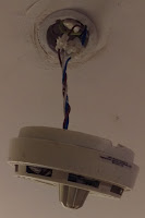
Over the holidays I broke the smoke alarm in my flat. Not the smoke alarm itself as such, but the mount that held it to the ceiling. Judging by the amount of various adhesives that were on the mount, it looks as though a previous occupant had actually broken the mount, but bodged together enough adhesive to hold it tenuously in place until they left.

It still works, thankfully, but it's just hanging from it's power lead.


First of all, take photos of the object against a plain background. Ideally pick a background which contrasts well against the object that you're trying to copy.


Editing the image in GIMP/Photoshop
Open the image in a photo editor, and crop any unnecessary bits out the picture.

Create a translucent layer above the current layer, so that you're working on the new layer, but can see through to the photo.
Use the paths tool to trace around the object as best you can, invert the selection and delete the contents. This should remove all the surrounding background bits.

Use the paths tool a few more times to create the cut-outs you require - for example in my case it's removing the centre piece and the screw holes.
Then make the working layer opaque, and fill the outline shape with a colour.

Save and export this image as a PNG.

OpenSCAD is meant to be able to import and extrude PNG files directly, but I've found it to be unreliable, so the below is a workaround that I've been using.

Converting to SVG using Inkscape
Open the edited image into a vector graphics editor, such as Inkscape.

Click on the image, right click and select "Trace Bitmap". Select "Edge Detection". If the image being used is simple enough, you can leave the default values, click OK, and then close the menu.

Drag the bitmap out the way (you can delete it now), and you should be left with an outline of the object. Fill the outline with a colour to make the object solid.


Save this SVG file.

Extruding the file in Blender
Open Blender.

Go to File, Import, Scalable Vector Graphics (SVG). Find the file and select it.
You may have to zoom quite far in to see the imported object.


Select the object and move it slightly,  you'll see a second outline object that gets left behind. Click on the outline object and delete it, you don't need it here, then replace the rest of the object.


Next we need to set the units of the object, so that we can scale it properly. Click the Scene properties tab on the right, and select Metric or Imperial from the units section.

Next, we scale the object.


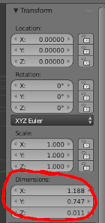
Press N to bring up the information about the object, and get the dimensions.

Set the X and Y scale here, but for the Z axis we need to extrude the flat image into a 3D object.

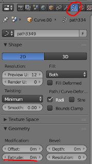
To do this, go to the right hand side and select object data, geometry, extrude.

In the case of my project, I added a couple of extra objects to recreate the latches which were broken off the original mount.


Once this is done export to STL and you have a file ready to send to the 3D printer.

Left, the original broken mount, and right, the 3D printed replacement.