Sunday, 24 August 2014
New app / Major Update: Web Media Grabber
This is a replacement for my previous 'RSS Media Grabber' app. This version is no longer restricted to RSS feeds, and can retrieve media from most web sources - RSS, Web page, Twitter feed, etc. It is also no longer limited to certain media types, and can retrieve any file extensions listed by the user.
The previous version will remain available on the Play Store for a while, until users have migrated over (this version couldn't be released as a simple update due to an issue with package signing keys)
Usage
When using the app for the first time, use the menu button and select "Add New Source".
On the next screen, enter the URL for the feed, and give a folder name (this will be where the app stores the files it downloads - eg, if you enter "MyFolder", the directory will be sdcard/MediaGrabber/MyFolder/)
Enter the file types you wish to extract, separated by spaces as per the example, eg "jpg gif mp3" etc.
Select OK to return to the main screen, and select menu->Load sources. This will list all the sources you've added.
Select one of the sources to be prompted to retrieve the feed. Select OK and it will load the feed, grabbing any media with your chosen file extensions, and saving them to the folder.
You'll then be able to view the downloaded media through your app of choice.
Monday, 11 August 2014
Analog pedal to USB keyboard
A lot of my electronics junk box consists of old videogame peripherals, which are often tricky to re-purpose because of proprietary connectors, peripherals, etc.
These pedals, for example, connect to a Playstation steering wheel by a fairly normal 9-pin serial connector, but the wiring isn't standard. Even if it were, most modern PCs no longer have serial ports, so a serial to USB adapter would be needed, and a software solution to make the input useful.
What I'm really after is a drop-in system, that can provide input as if it were a regular keyboard or mouse. The easy way out would be to use a microcontroller to emulate one of those devices, but I want to avoid throwing one at every problem, so I'm going to opt for only using discrete components and a scavenged keyboard PCB.
![]() |
I'm going to re-purpose this keyboard PCB from the phone scanner project that I did a while ago. |

It also seems a shame not to make some use of the fine control of the analog input, so what I have in mind is a two-stage trigger type system - so that a light press of the pedal completes one key, and a complete press sends a second key. For example, a light press could be 'Ctrl', and the full press 'X', to create a pedal for the standard Cut shortcut.
So what's needed is to find a way to create a threshold for when to close the keyboard circuit and trigger the buttons. In order to so this, we can use a low battery circuit, such as the one shown here.
Rather than wait for the power to drop though, we will be using the pedals' potentiometer in place of R4 in the diagram. As the voltage will remain the same, using the pedal to change the low voltage level will change the sensitivity of the circuit, so that when pressed, the LED is triggered. We will also replace the LED in that circuit with an optocoupler, connected to the keyboard matrix for the key that we want.
To create the second stage of the trigger, another copy of the circuit is created, but using a higher value resistor in place of R3, and sharing the same R4 (the pedal). This one will trigger when the pedal is pressed further.
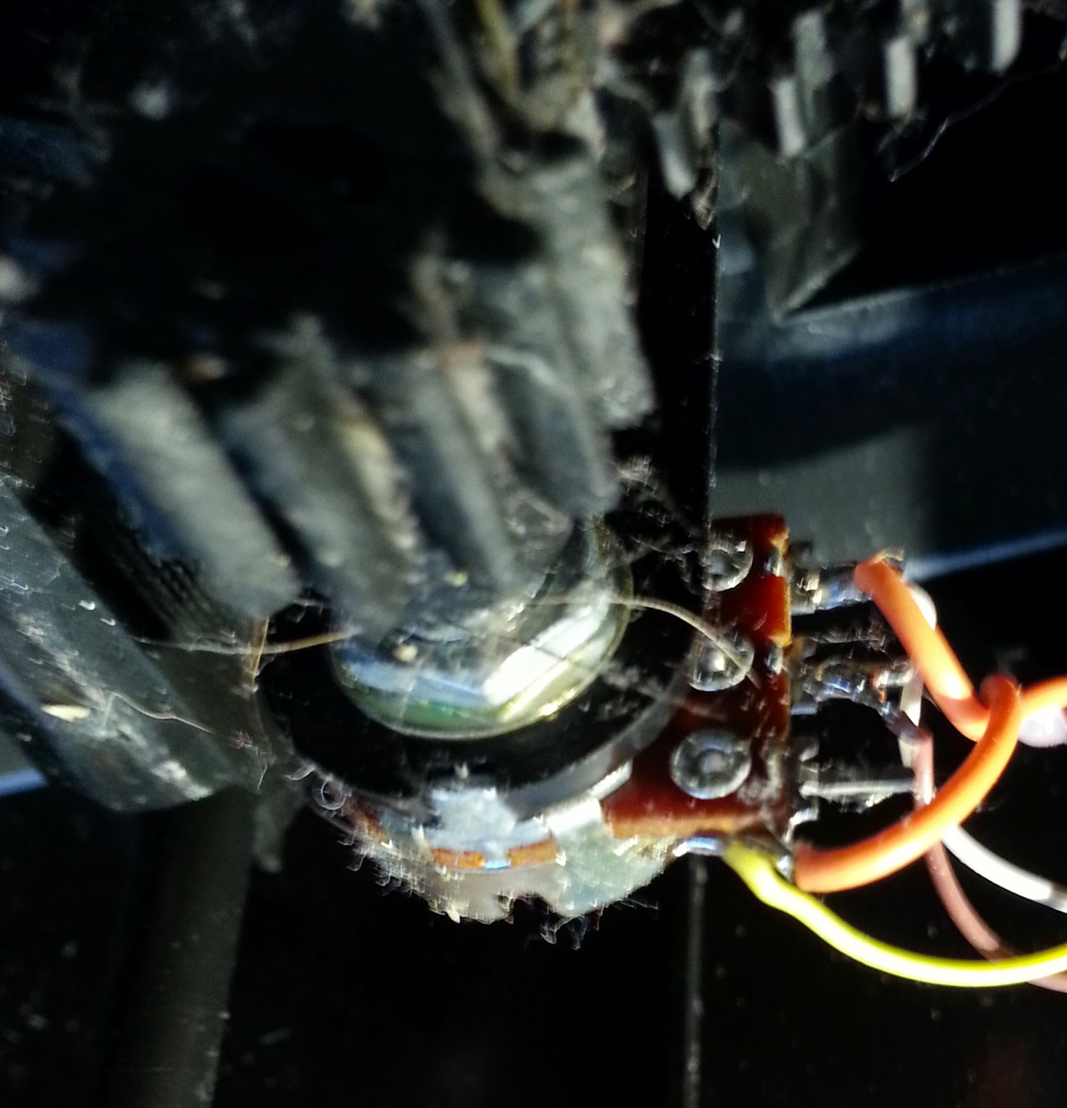
![]() |
The keyboard PCB. The old IDE cable is there to make it easier to patch together the key matrices - In the picture above the leads from the pedal circuit board are connected. |
Finally, power is added to the pedals from the keyboards USB connector - see left. This is sufficient to power both the keyboard and the pedal circuit
I have currently only done this for the right-hand pedal, but the same process could just as easily be done for the left (perhaps for other modifier keys - one shift, one ctrl etc).
A test of the pedal in various applications showed it to work, and has proved its usefulness for tedious key combinations in games (such as toggle run/slide etc)
Wednesday, 30 July 2014
App Update: Bluetooth Macro Input
The Bluetooth Macro Input app has been updated and is now available on Google Play.
New Features
As well as it's existing ability to send text files stored on phone, it is now possible to use voice recognition to transcribe voice to text and send that text via bluetooth in the same way, effectively allowing your phone to act as a dictation machine for your computer, without needing to install additional software on your computer.
Please note the voice recognition uses Google's voice recognition API. As a result, I do not have any control of the quality or accuracy of the voice recognition. It does also mean that Internet access is required to use the voice recognition feature.
Usage guide for the original file-based macro system can be found here.
Requirements Changes
Companion hardware is still required, see the original post for details.
The minimum required version of android is now Honeycomb (Android 3.0)
Sunday, 13 July 2014
Dog-controlled treat dispenser part 2
This is the second part of my project to create a dog treat dispenser that my dog, Jack, can operate on his own. For the first part, click here.
Building an enclosure
I thought about 3d-printing an enclosure for the control box, but before I commit the time and effort to designing and printing one, I want to make sure that the project works - and that Jack actually uses it.
So for now, I've managed to fit the electronics into an old business card box, with basic cut outs for the buttons and wiring. It's not pretty, but it works.
![]() |
The enclosure (the croc clips are for power - final version recycled a charger from a Playstation portable) |
The floor switch is connected to the control box by a length of old VGA cable - it's nice and sturdy, and has more than enough wires for this project.
![]() |
The components for the floor switch |
In use
I finally managed to get a short video clip of Jack using it
Future improvements
The floor switch is too light, as you can see in the video, when Jack uses it, he knocks it across the floor, so I've since mounted it to a bit of wood which helps hold it in place.
The small metal tin that I used to make the contact area larger & easier for Jack to use, ended up making the capacitive switch too sensitive - it basically became like a motion sensor - so I removed that, and used the original metal disc (about 15mm diameter) instead. Although the disc itself is smaller, it still manages to detect capacitance from contact anywhere on the switch, so it works just fine.
![]() |
The floor switch - unfortunately the hot glue made a bit of a mess, but it's all contained on the underside of the switch, and actually helps diffuse the light a bit. |
Source Code (Arduino cores for ATTiny2313
int latchPin = 8; int clockPin = 12; int dataPin = 11; int capBtn = 7; int plusBtn = 3; int minBtn = 4; int enabledLight = 5; int motorPin = 6; int treatCount = 0; int valToDisplay = 0; int timerBypassPin = 9; long myTime; boolean treatEnabled = false; void setup() { //set pins to output so you can control the shift register pinMode(latchPin, OUTPUT); pinMode(clockPin, OUTPUT); pinMode(dataPin, OUTPUT); pinMode(capBtn, INPUT); pinMode(enabledLight, OUTPUT); pinMode(motorPin, OUTPUT); pinMode(plusBtn, INPUT); pinMode(minBtn, INPUT); pinMode(timerBypassPin, INPUT); digitalWrite(motorPin, LOW); digitalWrite(enabledLight, LOW); treatCount = 3; } void loop() { if (digitalRead(plusBtn) == HIGH) { treatCount++; if (treatCount > 8) { treatCount = 8; } delay(500); } if (digitalRead(minBtn) == HIGH) { treatCount--; if (treatCount < 0) { treatCount = 0; } delay(500); } if (digitalRead(timerBypassPin) == HIGH) { treatEnabled = true; } if ( ((millis() - myTime) < 0) || ((millis()-myTime) >= 3600000) ) { myTime = millis(); treatEnabled = true; } digitalWrite(enabledLight, treatEnabled); if (digitalRead(capBtn) == HIGH) { if (treatEnabled) { digitalWrite(enabledLight, LOW); treatEnabled = false; treatCount--; digitalWrite(motorPin, HIGH); delay(3000); digitalWrite(motorPin, LOW); } } switch (treatCount) { case 0: valToDisplay = 0; break; case 1: valToDisplay = 1; break; case 2: valToDisplay = 3; break; case 3: valToDisplay = 7; break; case 4: valToDisplay = 15; break; case 5: valToDisplay = 31; break; case 6: valToDisplay = 63; break; case 7: valToDisplay = 127; break; case 8: valToDisplay = 255; break; } digitalWrite(latchPin, LOW); shiftOut(dataPin, clockPin, MSBFIRST, valToDisplay); digitalWrite(latchPin, HIGH); }
Tuesday, 24 June 2014
Dog-controlled treat dispenser
I picked up one of these treat dispensers from Maplins on a whim - one of those "I'm-sure-I'll-find-a-use-for-this-someday" things. Subsequently I started wondering if I could train my dog, Jack, to use it (with some modifications, obviously)
An initial attempt involved simply wiring a switch to a footpedal for Jack to step on. That lasted all of 10 seconds as the plastic lid I'd repurposed as a pedal cracked under his weight.
One of the things that attracted me to the gadget in the first place was the capacitive button that it used. A quick test with my phone screen showed that dog's paws can operate capacitive switches.
Simply extending the leads alone wouldn't be enough. Although I want to give Jack the freedom to get his own treats, I still want to keep control over how many!
The touch sensors board has simple connections - just power, and leads out to the motor. I didn't really want to waste time modifying the board, as it's all small surface-mount components. Since I know the motor was only driven one direction by the board, I simply connected an optocoupler to the motor outputs. A couple of pull-up resistors later and the switch was done.
I connected a metal lid in place of the small capacitive disc to make it more dog-friendly.
Now onto the human's control system..
My original plan was to use something web connected such as an old android device, so that I could give Jack treats whilst out at work, but in practice, it was totally overkill, so I opted for a microcontroller based system instead.
The only controls I really need are to limit the number of available treats, set a time limit so he doesn't eat them all at once, and a way to see how many were available.
I found an old PCB with two buttons on it in my junk box. One button to add a treat, one to remove.
For a display I went with a 10-segment LED, controlled by a shift register. Due to the limitations of the shift register, the maximum treats available at any one time is 8 - which is more than enough anyway. The remaining 2 LEDs are left unused.
The time limit I chose to fix at 1 hour in the microcontroller. As it's impossible to precisely measure the amount of treats that will be dispensed, the motor was set to a 3 second interval.
Finally I added a small LED module to the pedal, that lights when the timer ticks down and a treat is available, so that Jack could see when he can get a treat. According to the Pavlovian theory, he should soon learn that light=treat.
As with other projects I opted for using an Attiny (in this case the 2313) with the Attiny arduino cores, as they make it nice and easy to prototype with Arduino and switch to a regular AVR for the end product.
Stay tuned for part 2 - building an enclosure for it, some pictures of the completed project, source code, and hopefully some pictures/video of Jack using it.
UPDATE - Part 2 is now available here.
An initial attempt involved simply wiring a switch to a footpedal for Jack to step on. That lasted all of 10 seconds as the plastic lid I'd repurposed as a pedal cracked under his weight.
One of the things that attracted me to the gadget in the first place was the capacitive button that it used. A quick test with my phone screen showed that dog's paws can operate capacitive switches.
Simply extending the leads alone wouldn't be enough. Although I want to give Jack the freedom to get his own treats, I still want to keep control over how many!
The touch sensors board has simple connections - just power, and leads out to the motor. I didn't really want to waste time modifying the board, as it's all small surface-mount components. Since I know the motor was only driven one direction by the board, I simply connected an optocoupler to the motor outputs. A couple of pull-up resistors later and the switch was done.
![]() |
The finished capacitive button PCB with optocoupler |
I connected a metal lid in place of the small capacitive disc to make it more dog-friendly.
Now onto the human's control system..
My original plan was to use something web connected such as an old android device, so that I could give Jack treats whilst out at work, but in practice, it was totally overkill, so I opted for a microcontroller based system instead.
The only controls I really need are to limit the number of available treats, set a time limit so he doesn't eat them all at once, and a way to see how many were available.
I found an old PCB with two buttons on it in my junk box. One button to add a treat, one to remove.
![]() |
The salvaged button PCB (I believe it once belonged to a toaster...) |
For a display I went with a 10-segment LED, controlled by a shift register. Due to the limitations of the shift register, the maximum treats available at any one time is 8 - which is more than enough anyway. The remaining 2 LEDs are left unused.
![]() |
The 10 segment display (3 treats available) - the bottom 2 LEDs are not used. |
The time limit I chose to fix at 1 hour in the microcontroller. As it's impossible to precisely measure the amount of treats that will be dispensed, the motor was set to a 3 second interval.
Finally I added a small LED module to the pedal, that lights when the timer ticks down and a treat is available, so that Jack could see when he can get a treat. According to the Pavlovian theory, he should soon learn that light=treat.
![]() |
The LED module (it's just from one of those battery operated 'cupboard lights' you see in nearly every pound shop) - for this project I just connected a jumper over the button. |
As with other projects I opted for using an Attiny (in this case the 2313) with the Attiny arduino cores, as they make it nice and easy to prototype with Arduino and switch to a regular AVR for the end product.
Stay tuned for part 2 - building an enclosure for it, some pictures of the completed project, source code, and hopefully some pictures/video of Jack using it.
UPDATE - Part 2 is now available here.
Tuesday, 10 June 2014
Android App: RSS Media Grabber
My second android app is now available on the Google Play store. It's a port of a desktop Java application I wrote a while back, which will retrieve image media from RSS feeds - useful for web comics/cartoons, pic-of-the-day sites etc.
Usage
When using the app for the first time, use the menu button and select "Add New Source".
On the next screen, enter the URL for the feed, and give a folder name (this will be where the app stores the files it downloads - eg, if you enter "MyFolder", the directory will be sdcard/RSSMediaGrabber/MyFolder/)
Select OK to return to the main screen, and select menu->Load sources. This will list all the RSS feeds you've added.
Select one of the feeds to be prompted to retrieve the feed. Select OK and it will load the feed, grabbing any image media, and saving them to the folder.
You'll then be able to view the downloaded media through your photo app of choice.
Future development plans
Support/Feedback
As with my other apps, it's free (ad-supported), and I welcome feedback. Unfortunately I'm not in a position to offer any kind of official support for this, so use entirely at your own risk. If you have any trouble with it, then feel free to contact me on twitter/G+/leave a comment, and I'll try to help as and when I can, but I make no guarantees!
Any feedback, particularly with regard to different phone/tablet hardware and android versions is appreciated.
Usage
When using the app for the first time, use the menu button and select "Add New Source".
On the next screen, enter the URL for the feed, and give a folder name (this will be where the app stores the files it downloads - eg, if you enter "MyFolder", the directory will be sdcard/RSSMediaGrabber/MyFolder/)
Select OK to return to the main screen, and select menu->Load sources. This will list all the RSS feeds you've added.
Select one of the feeds to be prompted to retrieve the feed. Select OK and it will load the feed, grabbing any image media, and saving them to the folder.
You'll then be able to view the downloaded media through your photo app of choice.
Future development plans
- Wider media selection (MP3 for podcasts etc).
- Integrated media viewer/player
- Scheduling to check feeds at set intervals.
Support/Feedback
As with my other apps, it's free (ad-supported), and I welcome feedback. Unfortunately I'm not in a position to offer any kind of official support for this, so use entirely at your own risk. If you have any trouble with it, then feel free to contact me on twitter/G+/leave a comment, and I'll try to help as and when I can, but I make no guarantees!
Any feedback, particularly with regard to different phone/tablet hardware and android versions is appreciated.
Thursday, 22 May 2014
Android App: Bluetooth Macro Input
UPDATE - Please note this version of the Bluetooth Macro Input app is no longer supported. Although it's still on the Play store, it will not be updated in future. Please consider migrating to the new Bluetooth Macro and Voice Input app instead.
A while ago I posted this snippet of Arduino code for an upcoming project. Unfortunately with a looming redundancy and several courses on the go at the moment I've not had the free time to follow up until now.
All the code does is read a character from the serial pins of the arduino, then outputs that character as a keyboard keystroke using the keyboard emulation functionality of the Arduino Leonardo variants.
The rest of the hardware is very simple - just a bluetooth serial module, such as one of these - connected to those pins. There's just 4 pins - power, ground, TX and RX.
With that done, and the arduino sketch uploaded, the rest of the work is in the android application, which is now available for download by clicking the button below.
What it does
You can provide a library of snippets of text on your devices external storage (any ASCII filetype is fine), and then this app can access them, and send them via bluetooth to the arduino hardware, which emulates a USB keyboard and types the contents out.
This is handy for maintaining a library of code/command snippets that you might want to use across different computers or devices. (Or if, say, your day job requires you to often type the same thing on a computer that you have little control over software/config wise...)
Requirements
Usage
To run the app, first turn on bluetooth.
When you first run the app, you'll need to enter the MAC address of your bluetooth device - you should be able to find this in the docs of your serial device (or printed on it). Once done it should automatically connect.
Create or move your text snippet files to the a folder on the SD card under BluetoothMacroInput directory.
Use the Menu key in the app to bring up the menu, which is basically just the folder structure of the directory - click on your chosen file and it'll load it into the text view. Click 'Type' to have the device start typing your text.
Depending on your external hardware, you might need to adjust the delay value (if the typed text is garbled, then you need to increase the number)
Future Development plans
Support/Feedback
Unfortunately I'm not in a position to offer any kind of official support for this, so use entirely at your own risk. If you have any trouble with it, then feel free to contact me on twitter/G+/leave a comment, and I'll try to help as and when I can, but I make no guarantees!
Any feedback, particularly with compatibility on different hardware (both android devices and Bluetooth/keyboard hardware) will be much appreciated.
A while ago I posted this snippet of Arduino code for an upcoming project. Unfortunately with a looming redundancy and several courses on the go at the moment I've not had the free time to follow up until now.
All the code does is read a character from the serial pins of the arduino, then outputs that character as a keyboard keystroke using the keyboard emulation functionality of the Arduino Leonardo variants.
The rest of the hardware is very simple - just a bluetooth serial module, such as one of these - connected to those pins. There's just 4 pins - power, ground, TX and RX.
With that done, and the arduino sketch uploaded, the rest of the work is in the android application, which is now available for download by clicking the button below.
What it does
You can provide a library of snippets of text on your devices external storage (any ASCII filetype is fine), and then this app can access them, and send them via bluetooth to the arduino hardware, which emulates a USB keyboard and types the contents out.
This is handy for maintaining a library of code/command snippets that you might want to use across different computers or devices. (Or if, say, your day job requires you to often type the same thing on a computer that you have little control over software/config wise...)
Requirements
- The hardware described above.. Without it, the app is kinda pointless.
- Supports versions of android from 2.2 (Froyo) upward, though only tested on a Samsung Galaxy S3.
- Bluetooth serial device (115200 bps)
- Permissions
- Requires bluetooth and external storage access.
Usage
To run the app, first turn on bluetooth.
When you first run the app, you'll need to enter the MAC address of your bluetooth device - you should be able to find this in the docs of your serial device (or printed on it). Once done it should automatically connect.
Create or move your text snippet files to the a folder on the SD card under BluetoothMacroInput directory.
Use the Menu key in the app to bring up the menu, which is basically just the folder structure of the directory - click on your chosen file and it'll load it into the text view. Click 'Type' to have the device start typing your text.
Depending on your external hardware, you might need to adjust the delay value (if the typed text is garbled, then you need to increase the number)
Future Development plans
- One-button input for frequently used commands.
- Mouse emulation using phone touchscreen/sensors
- Dynamic macro recording (using USB host passthrough for a keyboard)
- General UI improvements..
Support/Feedback
Unfortunately I'm not in a position to offer any kind of official support for this, so use entirely at your own risk. If you have any trouble with it, then feel free to contact me on twitter/G+/leave a comment, and I'll try to help as and when I can, but I make no guarantees!
Any feedback, particularly with compatibility on different hardware (both android devices and Bluetooth/keyboard hardware) will be much appreciated.
Subscribe to:
Posts (Atom)