Sunday, 17 May 2015

A literal "Swear Jar"

Recently at work, management instituted a ‘Swear Jar’ system, to try and limit the use of profanity in the office.

Personally, I really have no issue with swearing - words are just words, but many people don’t share that view, so I understand why they did it.


The problem for me is that now, whenever someone swears, there’s a chorus of people shouting “Swear Jar!” at the person who swore. This, to me, is far more annoying than the swearing ever was.

It give me an idea though. What if the phrase “Swear Jar”, was taken more literally - a jar which swears at you when you put money in?

So, yeah, that’s the flimsy premise of this project. Read on for the full write up, or just watch the video of it in action below. (It should really go without saying that the language in the video may be unsuitable for some people..)


The Jar
As a base, I picked up one of those basic coin-counting money boxes often found that those ‘gadget shops’ which tend to open up in shopping centers selling a bunch of battery-operated plastic junk for a few weeks before they inevitably fail.

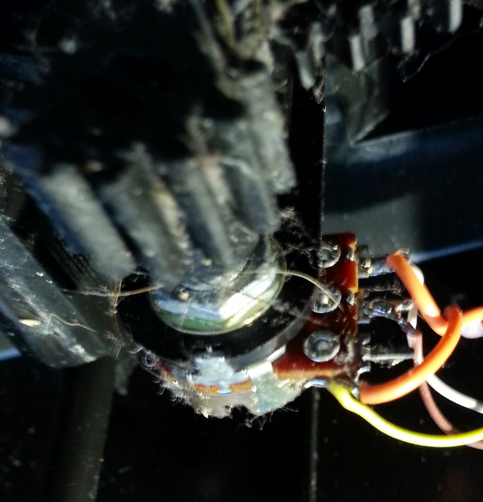
The coin mechanism is nothing special, essentially a slider which completes connections at different points to detect different coin values. there's not really anything else of value in the circuitry, it's all hidden behind epoxy blobs, so I scrapped everything else.

Audio
To provide the audio, I’m using an old MP3 player that I had in my junk bin - it’s essentially a 512MB memory stick with three control buttons and a headphone jack.


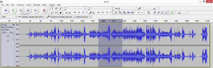
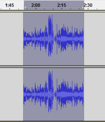
I enlisted a friend's help in trawling through movie clips on YouTube to get audio clips of profane movie quotes (this is where the previous post came from). The end result being a bunch of clips, all 3 seconds in length.

I wired up a small speaker from the junk bin. Fortunately the internal amplifier in the MP3 player was powerful enough to drive the speaker directly - as it's originally designed just for headphones, I thought it might not have sufficient power.

Controller
As this is just a novelty project, and I wanted to get it done and in the office before the swear jar idea was forgotten about, so I didn't really have time to delve too deeply into interfacing with the MP3 players circuitry. I opted to simply use a microcontroller to imitate human interaction. Conveniently, all the functionality I need from the MP3 player is obtained from just one button.

I opted for an ATTiny2313, using the arduino cores for convenience, and a relay to toggle the MP3 players button. Source code is below.

Power
Another complexity with this project is although the MP3 player doubles as a USB disk, powering it via the USB port only allows it to be used as a memory stick, and disables the MP3 playback functionality. Therefore the only other way to power the device is via it's AAA battery slot, so I required 2 power rails - 5v to drive the microcontroller, and 1.5v to power the MP3 player. This was achieved by using a 7805 to arrive at 5v for the micro, then using that 5v fed into an LM317 to provide 1.5 volts for the MP3 player. The main power input is 9v, which was originally intended to come from a battery, but at the last minute swapped for a wall supply (because I couldn't find a battery)

Block Diagram
The below shows how the different components fit together. As this is a frivolous novelty project, I'm not going to put together a full KiCad schematic - the most complex bit was the TS7805 and LM317 circuit, but there's plenty of existing documentation for those online already.


Timing is everything
The problem that quickly became evident is that the microcontroller has no feedback from the MP3 player, so cannot tell if a clip is playing, or even if the MP3 player is switched on. This is why the audio clips needed to all be the same length. There is also the issue of switching the MP3 player on, which requires a long press of the button. This is addressed in the setup function of the following code.

Code
int startPin = 2;
int emptyPin = 3;
int optoPin = 4;
int blinkPin = 5;
int isActive = 0;

void setup() {
  pinMode(emptyPin, INPUT);
  pinMode(startPin, INPUT);
  pinMode(optoPin, OUTPUT);
  pinMode(blinkPin, OUTPUT);
  digitalWrite(optoPin, HIGH);
  delay(1500);
  digitalWrite(optoPin, LOW);
}

void loop() {
  if (digitalRead(startPin)) {
    isActive = 1;
  } else if (digitalRead(emptyPin) == HIGH) {
    if (isActive) {
      playSound();
      isActive = 0;
    }
  }
}

void playSound() {
  digitalWrite(optoPin, HIGH);
  delay(100);
  digitalWrite(optoPin, LOW);
  delay(3200);
  digitalWrite(optoPin, HIGH);
  delay(100);
  digitalWrite(optoPin, LOW);
  delay(200);
}

Limitations
  • The MP3 player also has an auto switch-off function that causes it to turn itself off after a short period of time. This means that if no money is put in the swear jar for a while, the next time someone does, nothing happens, and requires the power to be cycled to reboot the whole thing.
  • The timing requirements are far too precise - even though all the audio clips used were 3 seconds, over time the slightest variances would add up, causing the microcontroller to lose sync with the audio.

Friday, 20 March 2015

How-to: Extract audio clips from Youtube videos and other media

So, I'm finally back after quite a long haitus to focus on my day job and studies. This post originated as a request from a friend who wanted to know how to extract snippets of audio from Youtube videos.

With this method the audio can come from any source that is playable in VLC (so, pretty much anything), but for the sake of this example I'm going to use Youtube, as that was the original request.

Step 1 - VideoDownloadHelper
On Firefox there's a plugin called VideoDownloadHelper which makes it easy to save videos from Youtube locally. If you use a different browser there's probably a similar plugin available.

Go to the Youtube page with the video that you want to save. VDH will auto detect the media and the toolbar button will light up.


Select the file - often there's quality options, usually it's best to just select medium. Save the file.


Step 2 - VLC

In VLC, go to File, Convert/Save, select the file, and click Convert.

In the dialog box, select Convert, and under Profile, select the output format that you require, and supply a destination file. Once that’s done, click Start. Wait for the progress bar to complete, and your output file will be done.

Step 3 - Audacity

Final step is to open that audio file in Audacity, play the audio to find the segment you want in the wave form.


Then select the section (just click and drag), then use the trim option (see icon).
The trim icon

Repeat the process until the desired segment of audio is isolated, then go to File, Export As, then export the file to the chosen format.

Monday, 27 October 2014

Remastering Tiny Core Linux

Tiny Core Linux is a lightweight Linux distribution designed for Live CD usage. Its low system requirements and small footprint also make it a good candidate for reviving older computers or as a base for building virtual machine appliances.

Unfortunately the remaster tool it includes, which is meant to allow for custom Live CDs to be created with chosen software pre-installed, seems to be buggy, and continually failed when I tried using it, so this is the alternative way I found to remaster TCL.

Step 1
Create a basic virtual machine and boot with the TCL Live CD. I used the CorePlus-current.iso, which has some extra software on there, but is still sub 100MB.


Once it's booted to the desktop select TC Install.


Select USB-HDD, whole disk and 'sda' options on the first screen.

Click through the next two screens (formatting options and boot options)


On the install type I checked the Installer Application option as I might need it in my intended application later, but it's optional.

Click through to the next screen where you're selected options will be repeated back to you, and select Proceed.

When it's done installing, shutdown the VM, remove the Live CD image and restart, so that it boots from the HD.


Step 2
Go to apps, and install the software that you require. In my case I installed Open JDK and Filezilla. (Filezilla also requires libiconv to be installed)


Reboot using the TC Exit options (from the menu go to Logout). The backup options there will essentially create a blank mydata.tgz file structure for you to use later.

Once rebooted, copy the /mnt/sda/tce1 folder off the VM to the host system/memory stick whatever (As I installed filezilla I FTP'd it to another server on my network.)

Step 3 (Optional)
On the host system, edit the mydata.tgz that you copied over, and add in any necessary files that you want on the Live CD. Thanks to the reboot that you did in step 2, mydata.tgz will have a basic file structure in place, that maps to the home and opt directories of the live CD. Also it puts in a couple of SH scripts, bootlocal.sh and shutdown.sh - these handle things that you want to execute on boot and shutdown respectively, edit those if you need to.

Step 4
Use an ISO editor (I used ISO Master).
Open the LiveCD, and navigate to it's 'cde' directory
Copy your mydata.tgz to the ISO, and replace its onboot.lst, and 'optional' directory with your own.

Navigate back to the ISOs /boot/isolinux directory and edit the isolinux.cfg file.
Find the line

TIMEOUT 600

This line causes it to sit on the bootloader screen for 60 seconds, unless the user selects and option.
I want my live CD to boot without user interaction, and that delay is redundant, so I edited it to

TIMEOUT 10

which allows a 1 second delay before continuing to boot the default option.


Save the edited ISO. To test, setup a blank VM like you did in step 1, and select the edited ISO as the boot medium. TCL should load, with your apps and files already there.

Sunday, 19 October 2014

HD44780 LCD to Raspberry Pi

My interest in electronics initially started as a result of PC modding back in the late 90s/early 2000s. Back then, most desktop computers were typical beige boxes - it was all about the internal hardware, not the design of the system itself, and it fell to the users to make then any more interesting than that.

A common mod was to install a LCD screen into the front of the desktop to display things such as system stats (CPU, Memory, temperature), notifications (Email/MSN/ICQ!) or the currently playing track on Winamp.

My old desktop PC has long since been retired, but I still have the LCD that I used, and now I've found an excuse to use it again.

Nostalgia aside, I have a project underway that is going to require a headless Raspberry Pi. While it's easy enough to SSH into the Pi and get to a terminal from another computer, it would also be handy to have at-a-glance stats available.

Fortunately, there's a way to connect a HD44780 LCD (standard text one like mine) to the Pi, using the standard GPIO pins, and leaving the serial pins free (which I'll need for another part of the project).

The thing to be wary of when looking for instructions on connecting one of these displays to a Raspberry Pi is that there are many 'LCD backpacks' and specially designed accessories out there. I'm not using any of those, simply the Pi, the LCD, and a potentiometer to adjust contrast on the display.

Adafruits wiring guide is a good start. While it's aimed at 16x2 displays, it does apply to those of other sizes (the one I'm using is 4x20. They keep referencing their 'Pi Cobbler', though this is simply a breakout board they sell, and it's easy enough to map to the standard Pi pins.
 
A couple of points worth reiterating - the GPIO pins are designed for 3.3v operation, but the LCD for 5v. To avoid 5v being sent to the GPIO, connect the RW pin of the LCD to ground. Also worth noting is the difference between LED and EL backlight. EL has a higher current draw, so trying to power it from the Pi might overload it (LED however is fine). The displays can operate just fine without the backlight, so it's optional anyway. Mine is EL, but I don't really need it, so just left it unconnected.

I was relieved to see that LCDproc is still around. This was the software I used back with my old desktop, so I chose to stick with this instead of the Python solution Adafruit suggest. The pins that they recommend using are slightly different, but can be adjusted in the LCDproc config.

  • To install LCDproc on the Pi, run
    • sudo apt-get install lcdproc
  • Open the config file
    • sudo nano /etc/LCDd.conf 
  • find the line
    • Driver=curses
  • and replace with
    • Driver=hd44780 
  • Find (Ctrl+W) the [hd44780] section and change the ConnectionType line to
    • ConnectionType=rpi 
  • Underneath add the pin mappings in the format shown below 
D7=18
D6=23
D5=24
D4=25
EN=8
RS=7 
 
Even though there is a driver file (hd44780.so) in the driver path, it doesn't seem to work.
Some Google searching found someone else with a similar issue and a replacement driver file, see steps 4 through 10 on there. (though note there's some differences in the rest of their setup to mine, so beware.)

Once that's done, restart LCDd with
  • sudo service LCDd restart
and you should see some text on your LCD!

The default LCDProc screen - the ribbon cable at top left connects to the Pi GPIO.
The small PCB in the top right is a 3.3v to 5v level converter that is to be used for a different project.


Sunday, 21 September 2014

New App/Update: Bluetooth Macro and Voice Input

This new app is an update to my previous Bluetooth Macro Input app. Unfortunately, for technical reasons, I could not issue this as an update to the existing app.


The new version focuses more on the voice recognition and transcription features of the app,

Now any macros you store in the Macros subfolder can be selected by voice. For example, if you store your macros in
<DEVICE STORAGE>/BluetoothMacroFiles/
and have a macro called
<DEVICE STORAGE>/BluetoothMacroFiles/Macros/Hello world.txt

Then the voice command "Hello World" can be used to load and play back that macro.

Usage
Usage guide for the original file-based macro system can be found here.
Previous update notes are available here.

Requirements Changes
Companion hardware is still required, see the original post for details.

The minimum required version of android is Honeycomb (Android 3.0)

Sunday, 24 August 2014

New app / Major Update: Web Media Grabber


This is a replacement for my previous 'RSS Media Grabber' app. This version is no longer restricted to RSS feeds, and can retrieve media from most web sources - RSS, Web page, Twitter feed, etc. It is also no longer limited to certain media types, and can retrieve any file extensions listed by the user.
The previous version will remain available on the Play Store for a while, until users have migrated over (this version couldn't be released as a simple update due to an issue with package signing keys)


Usage
When using the app for the first time, use the menu button and select "Add New Source".
On the next screen, enter the URL for the feed, and give a folder name (this will be where the app stores the files it downloads - eg, if you enter "MyFolder", the directory will be sdcard/MediaGrabber/MyFolder/)
Enter the file types you wish to extract, separated by spaces as per the example, eg "jpg gif mp3" etc.
Select OK to return to the main screen, and select menu->Load sources. This will list all the sources you've added.
Select one of the sources to be prompted to retrieve the feed. Select OK and it will load the feed, grabbing any media with your chosen file extensions, and saving them to the folder.

You'll then be able to view the downloaded media through your app of choice.

Monday, 11 August 2014

Analog pedal to USB keyboard


A lot of my electronics junk box consists of old videogame peripherals, which are often tricky to re-purpose because of proprietary connectors, peripherals, etc.

These pedals, for example, connect to a Playstation steering wheel by a fairly normal 9-pin serial connector, but the wiring isn't standard. Even if it were, most modern PCs no longer have serial ports, so a serial to USB adapter would be needed, and a software solution to make the input useful.

What I'm really after is a drop-in system, that can provide input as if it were a regular keyboard or mouse. The easy way out would be to use a microcontroller to emulate one of those devices, but I want to avoid throwing one at every problem, so I'm going to opt for only using discrete components and a scavenged keyboard PCB.

I'm going to re-purpose this keyboard PCB from the phone scanner project that I did a while ago.

The pedals themselves are essentially just a couple of potentiometers, so in it's simplest form, the contacts for a key could be wired to the pedal. This would mean that as the pedal is pressed, it will reach a point where the resistance is low enough for the signal to pass, however this is quite a simplistic option.


It also seems a shame not to make some use of the fine control of the analog input, so what I have in mind is a two-stage trigger type system - so that a light press of the pedal completes one key, and a complete press sends a second key. For example, a light press could be 'Ctrl', and the full press 'X', to create a pedal for the standard Cut shortcut.

So what's needed is to find a way to create a threshold for when to close the keyboard circuit and trigger the buttons. In order to so this, we can use a low battery circuit, such as the one shown here.

Rather than wait for the power to drop though, we will be using the pedals' potentiometer in place of R4 in the diagram. As the voltage will remain the same, using the pedal to change the low voltage level will change the sensitivity of the circuit, so that when pressed, the LED is triggered. We will also replace the LED in that circuit with an optocoupler, connected to the keyboard matrix for the key that we want.

To create the second stage of the trigger, another copy of the circuit is created, but using a higher value resistor in place of R3, and sharing the same R4 (the pedal). This one will trigger when the pedal is pressed further.
The circuit, with a test potentiometer in place (the upside-down PCB just contains some screw terminals for attaching the potentiometer - see right) Each pair of leads on the left go to the respective terminals on the keyboard PCB (below)
The screw terminal on the underside (on a separate PCB as I scavenged it from the junk box)

The keyboard PCB. The old IDE cable is there to make it easier to patch together the key matrices - In the picture above the leads from the pedal circuit board are connected.


Finally, power is added to the pedals from the keyboards USB connector - see left. This is sufficient to power both the keyboard and the pedal circuit


I have currently only done this for the right-hand pedal, but the same process could just as easily be done for the left (perhaps for other modifier keys - one shift, one ctrl etc).


A test of the pedal in various applications showed it to work, and has proved its usefulness for tedious key combinations in games (such as toggle run/slide etc)