Thursday, 28 January 2016

Copying objects for 3D printing without a 3D scanner


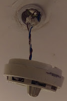
Over the holidays I broke the smoke alarm in my flat. Not the smoke alarm itself as such, but the mount that held it to the ceiling. Judging by the amount of various adhesives that were on the mount, it looks as though a previous occupant had actually broken the mount, but bodged together enough adhesive to hold it tenuously in place until they left.

It still works, thankfully, but it's just hanging from it's power lead.


First of all, take photos of the object against a plain background. Ideally pick a background which contrasts well against the object that you're trying to copy.


Editing the image in GIMP/Photoshop
Open the image in a photo editor, and crop any unnecessary bits out the picture.

Create a translucent layer above the current layer, so that you're working on the new layer, but can see through to the photo.
Use the paths tool to trace around the object as best you can, invert the selection and delete the contents. This should remove all the surrounding background bits.

Use the paths tool a few more times to create the cut-outs you require - for example in my case it's removing the centre piece and the screw holes.
Then make the working layer opaque, and fill the outline shape with a colour.

Save and export this image as a PNG.

OpenSCAD is meant to be able to import and extrude PNG files directly, but I've found it to be unreliable, so the below is a workaround that I've been using.

Converting to SVG using Inkscape
Open the edited image into a vector graphics editor, such as Inkscape.

Click on the image, right click and select "Trace Bitmap". Select "Edge Detection". If the image being used is simple enough, you can leave the default values, click OK, and then close the menu.

Drag the bitmap out the way (you can delete it now), and you should be left with an outline of the object. Fill the outline with a colour to make the object solid.


Save this SVG file.

Extruding the file in Blender
Open Blender.

Go to File, Import, Scalable Vector Graphics (SVG). Find the file and select it.
You may have to zoom quite far in to see the imported object.


Select the object and move it slightly,  you'll see a second outline object that gets left behind. Click on the outline object and delete it, you don't need it here, then replace the rest of the object.


Next we need to set the units of the object, so that we can scale it properly. Click the Scene properties tab on the right, and select Metric or Imperial from the units section.

Next, we scale the object.


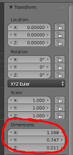
Press N to bring up the information about the object, and get the dimensions.

Set the X and Y scale here, but for the Z axis we need to extrude the flat image into a 3D object.

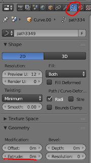
To do this, go to the right hand side and select object data, geometry, extrude.

In the case of my project, I added a couple of extra objects to recreate the latches which were broken off the original mount.


Once this is done export to STL and you have a file ready to send to the 3D printer.

Left, the original broken mount, and right, the 3D printed replacement.

Saturday, 26 December 2015

Audio Controlled Christmas Lights

So it's the run up to Christmas, and at work we're having a desk decorating competition. This of course means lights, and an excuse for some colourful, blinky-type projects.

Most supermarkets are selling these battery operated chains of coloured LED lights for a couple of quid. They run off 3 AA batteries (4.5v) and are just static lights.


If you look closely there's actually 3 wires – this is likely because the different colour LEDs have different voltage drops. When I get to dismantling them later we'll know which are on which wire, but my guess is that red and orange are on one line, green and blue on the other. Turns out I was right.

My idea is very simple, wire an transistor onto each line so that they can be controlled independently, then connect a stereo jack to the base, with each channel (left/right) connecting to alternating transistors, so each audio channel will control one strand of lights. The principle is similar to the design I used on the space invaders alarm clock project, but instead of the alternating current being responsible for changing the colour, it'll be the audio channel.


The circuit diagram. The only components I need to add were the transistors, the stereo socket, and a USB cable for power (the resistors were already part of the assembled lights.)


The finished circuit, with the ever-useful TicTacs box enclosure.


The flickering of the lights works, but the frequency is very rapid, which seems to stop the LEDs reaching full brightness. Potentially this could be alleviated by adding capacitors to smooth out the switching, but as the effect varies quite drastically depending on audio source, it's not really an issue. The next challenge is finding a playlist that uses the lights to best effect!


Sunday, 13 December 2015

Car Smoke Machine Pt 3

This is the final part of an on-going series of posts about a project to build and install a smoke machine in my car... for science or something...

If you missed the first two parts, they can be found here

So far we've got an e-Cigarette and an air pump wired together to produce a cloud of smoke. Now what we need is to find a way to control it and install it covertly in my car.

I don't want the trap to spring too early, I need to give them time to get comfortable in the car and get started, for it to be believable.

Also, the motor driver chip will need some logic control, so it makes sense to use a microcontroller to provide the logic and the timings.

As I mentioned in the previous post, left to it's own devices, the eCig's coil gets rather hot, so in order to counter that I wanted the microcontroller to only switch it on in 5 second bursts, then wait 5 seconds for it to cool down.

I used an ATTiny26, for no technical reason other than I have a lot of them spare.


Microcontroller code

 1 #define F_CPU 1000000UL
 2 
 3 #include <avr/io.h>
 4 #include <util/delay.h>
 5 
 6 #define CONTROL_PORT           PORTA
 7 #define output_low(port,pin)   port &= ~(1<<pin)
 8 #define output_high(port,pin)  port |= (1<<pin)
 9 #define delay(a)               _delay_ms(a)
10 #define smokeEnable            PA2
11 #define setInput(ddr,pin)      ddr &= ~(1 << pin)
12 #define isInputHigh(pinr,pin)  pinr & (1<<pin)
13 
14 int isRunning = 0;
15 int secCount = 0;
16 
17 int main(void) {
18     setup();
19     while (1) { loop(); }
20 }
21 
22 void setup() {
23     DDRA = 0xFF;  // all outputs
24     setInput(DDRB, PB6);
25 }
26 
27 void loop() {
28         if (isInputHigh(PINB, PA6)) {
29                 if (!isRunning) {
30                         delay(10000);
31                         output_high(CONTROL_PORT, smokeEnable);
32                         isRunning = 1;
33                 } else {
34                         secCount++;
35                         if (secCount > 5) {
36                                 output_low(CONTROL_PORT, smokeEnable);
37                                 delay(5000);
38                                 secCount = 0;
39                                 output_high(CONTROL_PORT, smokeEnable);
40                         }
41                 }
42         } else {
43                 output_low(CONTROL_PORT, smokeEnable);
44                 isRunning = 0;
45         }
46         delay(1000);
47 }
48 


The finished circuit
Click to enlarge
The Videos
I was hoping to use this to prank as many people as possible, and get some good video footage, but unfortunately only 2 of the videos were really usable. The first, is Craigs "We're all gonna die lads!" reaction, and the second, is Bethany's obliviousness to the cloud of smoke forming around her. Enjoy.


Sunday, 15 November 2015

Car Smoke Machine


A prank that's been doing the rounds in my office is that if you leave your car keys unattended on your desk, you can expect that your car probably won't be where you left it when you leave for the evening.

I've been kicking around ideas on how to improve on this gag, and at the same time defend my car from it happening to me.

My idea was to orchestrate a scenario of deliberately leaving my key for someone to try and move my car, and setting up a surprise for them when they get in. If I could make the car appear to be breaking down, would they own up thinking they broke the car, or just put the key back and deny all
knowledge?

So, what do we need to make it seem a car's breaking down? Noise and smoke.

The noise is quite simple, take a vibration motor from an Xbox/Playstation controller, wire it up and put it in a small container of screws & random bits of metal, so when it vibrates, we get a metallic rattle.

The smoke, not so easy. All the consumer smoke machines I could find required mains power, and would be far too bulky to conceal in the car, so I have to roll my own.

Thankfully vaping and e-cigarettes have made battery powered, small, smoke producing devices quite cheap and readily available.


I purchased a few e-cigarette "Atomisers" from amazon and did some testing. See this post for a write up of how I wired up the eCigarette.


Unless there's a person 'drawing' on the device, the smoke cloud just sits there, so I'm going to need to create a pump or fan to force air through the atomiser.

A quick test with some old computer fans that I had lying around showed that they weren't powerful enough, so I found a battery operated air-mattress pump that would do the trick.


The pump appears quite bulky, but it runs on 4 D Cell batteries. As we're not going to need those, a large proportion can be cut away, streamlining the whole thing.


To drive the motor of the pump, I'm going to use the same SN754410 that I'm using to power the e-Cigarette (this is why I used the SN754410 in the previous post, as it's capable of driving two motors, or in this case, one motor and one e-Cigarette.)

This is how the original circuit was planned. The input voltage is 12v as this is the most readily available source in the car. (The EN pins and motor logic will all be connected to the microcontroller - left off in this diagram).
Testing this circuit turned out that 1 amp per 'motor' wasn't powerful enough to drive the pump, so I ended up putting the eCigarette coil and the pump motor in series, and joined the two motor channels of the SN754410 in parallel to double the available current. This isn't an ideal solution, as the resulting heat of the eCig coil is a bit excessive, but I only need it to work in short bursts, and I can control that from the micro.

The revised circuit


Here is the first working test of the smoke machine:

As the pump makes enough noise, I decided that the vibration motor was a bit unnecessary, so left that off the final design. Essentially the device is a simple micro-controlled smoke-machine.


Thursday, 5 November 2015

Wiring an interface to an e-Cigarette


I'm currently working on a project that requires the use of an e-cigarette.
I'm not a smoker, so as far as that aspect is concerned, I might be a little off on the terminology, but eCigarettes, vapourisers, whatever you want to call them, essentially follow the same principle. There's a battery, a small reservoir of vaping fluid, a wick, and a wire coil.


Current is passed through a coil which causes it to heat up, in turn heating a wick soaked in fluid which turns it into a vapour.
We can ignore the battery component, it's only really the wire coil I need for the project. I do however need to control it, so I needed to find a way to interface it.


The coil connects to the battery by a screw-type connector which appears to be specifically for these devices. In addition, the connector also contains a small gap which acts as an air inlet for the user to take a drag on it.

This causes problems when trying to create a connection, as connectors run the risk of blocking the inlet.

Coincidentally I found that a male TV aerial connector is an ideal size to create a push-fit connector. The next task is to decide how to control the current flow. Simply switching it on and leaving it will cause it to overheat.


Coils like this can be controlled in similar way to motors. In fact, the IC I'm going to use to control this is really designed for driving motors, but works fine for the purpose of this.

The chip is the SN754410 H-Bridge motor driver - which is completely overkill for this, but as this is forming a part of a larger project, the reasoning will become clearer later.

The pinout for the chip is available on the third page of this datasheet. Treat the vapouriser as if it was a motor - polarity/direction of travel doesn't matter.

For the motor drivers voltage I'm using 12v, which, again, is overkill for this part in particular, but the coils are very tolerant of it, and use the speed control function of the chip to control how hot the coil gets.

That's all for now, stay tuned for the 2nd part of this project...


Sunday, 30 August 2015

Writers Block Motivational Assistant

aka, electrocuting friends for fun and profit

One of my friends is a writer, and one of the common complaints I hear is that of “Writers block” - experiencing a creative slowdown and not being able to think of ideas to write.

I experience a similar thing with the projects I'm working on from time to time. A solution I've always sworn by is to just jump in and start doing something – even if it's crappy to begin with, it can always be edited later, and the process of actually taking action helps stir the creativity.

The discussion itself was enough for me to start thinking creatively for ways to overcome writers block. Think a cattle prod, combined with the movie Speed, and you get the idea.

As usual the full write up is below, or here's the video of it in action. Unfortunately there's not much to see, the shock wasn't strong enough to create much of a visible effect - it made my thumb twitch a bit, but seemed very dependent on where the electrodes were placed.


The hardware

As we're administering electric shocks to people with this project, in the interests of safety I didn't feel too comfortable DIY-ing the actual shock circuitry, so I picked up one of these reaction-test toys – the idea of the game each player holds one of the controllers, the light in the centre blinks red, as soon as it hits green, the last player to press their button gets a shock. Simple.
The shock game that's going to form a base for this project
The game in action

The bottom of the unit just contained the main switch, battery compartment and small speaker. None of these are needed in this project, so all found their way into the junk bin.

The top of the PCB just contains the main button (centre, surrounded by LEDs), a number of players button in the corner, and a few capacitors. The 4 LEDs around the edge were removed.


There was also a switch on the side which determined the severity of the shock - either a single one or multiple. I forgot to check which one was selected when I removed it, so that'll be a surprise when it's done. (This was connected to the green wires in the PCB picture below - effectively I've left the switch open)

I also cut away all the controller wires except for player one - that will be the one we're using.


The controller and it's circuitry


Interfacing & Software

How we're going to interface this is by wiring shut the player one button (so effectively it's always held down), and adding an optocoupler in place of the main game button. Then when receiving the signal to deliver a shock, a new game will be triggered, and player one will be shocked for pressing the button too early.


It looks like a steampunk torture device, but it works.
The wires on the controller side were re-wired to a couple of cheap pound-store bracelets, separated by a few 3d-printed plastic spacers and held together with copious amounts of hot glue.


The typical next step here would be to wire in a microcontroller, usb-serial converter and have the PC direct output that way, but I've done that dozens of times and felt like doing something different, so I'm going to use bluetooth and a Wiimote.

The Wiimote connects via bluetooth and contains several sensors. In truth, it's overpowered for this project, but it does give plenty of room for expansion in the future. We're going to use the vibration motors connections to link up to the shocker.


The dismantled Wiimote we're going to use

The connection itself is very straight-forward - a simple optocoupler between the shock toys' main 'play' button connections and the vibration motor output on the Wiimote.

Power is obtained with a 5V wall-wart supply, brought down to 3.3V for the Wiimote using an LM317.

The finished box and bracelet
The software
The source code for the application can be found on Github. Uses Bluecove and MoteJ libraries.

Update
The initial bracelet didn't work to well in testing, as the angle made it difficult to ensure both sides of the connection were in contact with the arm, so I put together an alternative using an old sweat band with a couple of pennies glued into it.

Inside

The new shock band


Saturday, 18 July 2015

In-car Bluetooth Stereo Mod

As the past few projects have been quite frivolous gadgets, this time I'm going to do something practical. It turns out this was actually one of the quicker projects I've done and makes a decent weekend project for anyone looking to make a quick upgrade to their cars audio system.

My car as an auxiliary audio input for connecting MP3 players etc. For this I purchased a bluetooth speaker adapter on Ebay for about a tenner.


It's a great device to connecting my phone for sat-nav, music etc, but there's a small annoyance in the fact that after getting in the car, it requires me to press and hold the power button for about 5 seconds before it'll turn on and connect to my phone. It's a bit of a first-world problem, granted, but it's kinda irritating, so I've been thinking about how to solve it.

Ideally, it should function like a built-in bluetooth adapter does in many new cars - as soon as the car is powered on, the bluetooth is powered on and connects to the phone.


After some experimenting with various approaches - microcontroller delays, 555 timers, I found the most functional circuit was a simple capacitor delay circuit, combined with a transistor NOT gate & optocoupler, so that the optocoupler is active, effectively holding down the adapter's power button, for 5 seconds, then switched off until the circuit loses power.


A rough schematic of the circuit I used


The completed circuit on top of the bluetooth adapter
Inside the bluetooth adapter.


Powering the circuit was simple enough - I already have a car 'cigarette lighter' to USB adapter with 2 USB ports - one powers the bluetooth adapter, and it powers on with the car ignition, so I added a USB plug to the timer circuit and used that.

Finally, I didn't want to leave exposed wires or circuit boards visible in the car - knowing my luck some paranoid idiot would freak and call the bomb squad or something, so I 3D printed a simple box enclosure which houses the adapter and the circuit nicely, the box itself nestling neatly in the centre console of my car.
The finished adapter in it's 3D printed box, ready to put in the car